
 WhatsApp: +86 16626708626
 Email:
  Phone: +86 16626708626
Description
Key Technical Specifications
| Parameter | Value |
|---|---|
| Manufacturer | Extreme Networks |
| Model Number | STK-RPS-150PS |
| Product Type | Plug-in redundant power-supply module |
| Primary Function | Backup power for supported stackable or standalone fixed switches |
| Rated Power | 150 W |
| Power Application | Non-PoE switch redundancy only |
| AC Input Voltage | 100–240 V AC |
| AC Input Frequency | 50–60 Hz |
| DC Output Voltage | 12 V DC |
| DC Output Current | 1.0 A minimum; 8.5 A or 13.0 A maximum, depending on supported application |
| Operating Temperature | 0 to 50°C (32 to 122°F) |
| Storage Temperature | −40 to 70°C (−40 to 158°F) |
| Operating Humidity | 5% to 95% non-condensing |
| Dimensions | 7.7 H × 2.04 W × 10.1 D in. / 19.6 H × 5.2 W × 25.7 D cm |
| Weight | 3.85 lb / 1.75 kg |
| Standalone Use | Supported |
| Shelf Compatibility | STK-RPS-150CH2 two-slot shelf or STK-RPS-150CH8 eight-slot shelf |
| Rack Installation | Supported when installed in a compatible RPS shelf |
| Connector Interface | 14-pin RPS connector with power, ground, RPS-present, status, and power-good signals |
| Lifecycle Status | Legacy network-infrastructure spare; verify current manufacturer supply and support status before a long-term last-time-buy |
| Stocking Recommendation | Min: 1 per critical compatible switch site or protected network zone; Max: based on commonality across sites, recovery-time target, and shelf capacity |
Extreme Networks specifies a 150 W redundant power supply with 100–240 V AC input, 12 V DC output, 0 to 50°C operating temperature, and compatibility with standalone use or the STK-RPS-150CH2 and STK-RPS-150CH8 shelves.
Product Introduction & Supply Chain Strategy
The Extreme Networks STK-RPS-150PS is a 150 W redundant DC power module for supported non-PoE stackable and standalone fixed Ethernet switches. It supplies backup power to maintain network availability if the primary switch power source fails. It can operate as a standalone unit or install into a two-slot or eight-slot RPS shelf for centralized rack deployment.
This product is a Brand New Surplus unit. It is not used, not pulled from a decommissioned plant, and not refurbished. All modules undergo rigorous quality verification to ensure OEM-level reliability. For a plant network, the relevant TCO is the avoided cost of losing PLC, HMI, SCADA, historian, or remote-I/O communications. Keep targeted buffer stock for critical switch groups, but use vendor consolidation and cross-site sharing for low-impact locations to control carrying cost and inventory turnover.
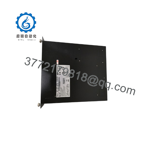
STK-RPS-150PS
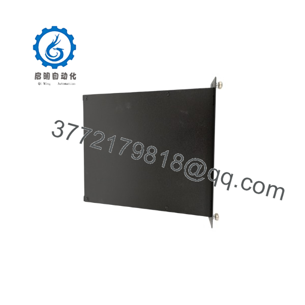
STK-RPS-150PS
Installation & Configuration Guide
Stage 1: Pre-Installation
- Identify the exact protected switch model and confirm it is approved for the STK-RPS-150PS. This module supports specified non-PoE Extreme Networks fixed switches only.
- Do not connect this RPS to a PoE-compliant fixed switch. Extreme Networks warns that doing so can damage the switch.
- Record the switch model, serial number, firmware revision, active network configuration, VLAN settings, port configuration, uplink status, redundancy topology, and current alarm state.
- Review the network maintenance window and confirm that temporary loss of switch power will not create a process, safety, control, or communication hazard.
- Notify operations and isolate affected automation or network services according to the approved change-control procedure.
- Apply lock-out/tag-out to the AC supply feeding the RPS if local electrical-safety rules require it.
- Use a grounded ESD wrist strap when handling the RPS module, switch RPS connector, or shelf-mounted module.
- Photograph the switch RPS port, RPS cable, shelf slot, AC cord routing, grounding arrangement, and module labels before installation.
- Inspect the RPS cable and connector for bent contacts, cracked housing, loose locking hardware, contamination, or damaged strain relief.
- Confirm that the RPS shelf, if used, is either an STK-RPS-150CH2 or STK-RPS-150CH8. A flat-blade screwdriver is required for shelf and power-supply installation.
Stage 2: Removal
- Power down both the protected switch and the RPS before connecting or disconnecting the RPS cable. Extreme Networks states that connecting an RPS to an operational switch can adversely affect the switch.
- Remove AC power from the existing RPS module or shelf and verify that the power LED is off.
- Disconnect the RPS cable by the connector housing. Do not pull the cable itself or apply side load to the switch RPS port.
- If the module is shelf-mounted, remove any retaining hardware or release mechanism according to the shelf design.
- Support the module during removal and avoid striking the connector face against the rack or shelf.
- Inspect the shelf connector and switch connector for damage or oxidation before installing the New Surplus unit.
- Label the removed module with asset information, observed fault symptoms, removal date, and test status for controlled engineering evaluation.
Stage 3: Installation
- Confirm the replacement nameplate reads STK-RPS-150PS and verify that the unit is intended for the installed non-PoE switch environment.
- For a standalone deployment, place the RPS in a stable, ventilated location with protected cable routing and access to an approved AC source.
- For a shelf deployment, install the module into an STK-RPS-150CH2 or STK-RPS-150CH8 shelf. Seat it evenly and secure it using the shelf’s specified retention method.
- Confirm that airflow around the module and shelf is not blocked by cable bundles, cabinet obstructions, or adjacent heat-generating equipment.
- Connect the RPS cable to the powered-down switch and the powered-down RPS. Confirm correct connector orientation and fully engage the locking hardware.
- Connect protective grounding and AC power according to the site electrical standard and equipment documentation.
- Verify that the RPS cable is routed separately from high-noise power conductors where practical and has adequate strain relief.
- Recheck that the target switch is non-PoE and listed as compatible before restoring power.
Stage 4: Power-On & Testing
- Power on the RPS first, then power on the switch. This is the manufacturer’s recommended connection sequence after cabling is complete.
- Check the RPS Power LED. A solid green LED indicates that AC input is within specification.
- If the Power LED remains off, verify the AC cord connection, AC outlet power, and AC cord condition. Test with a known-good power cord if permitted by site procedure.
- Confirm that the switch boots normally and that the RPS-present or power-good status appears as expected in the switch interface, event log, or network-management system.
- Verify switch uplinks, VLAN operation, industrial protocol traffic, controller communication, HMI access, remote I/O connectivity, and redundancy status.
- Where approved by the site change procedure, perform a controlled primary-power-loss test to confirm that the RPS provides the expected backup function without disrupting required network communications.
- Record the RPS serial number, deployment location, protected switch asset number, test results, firmware/configuration references, installation date, and next inspection date.
Firmware/Software Versions & Upgrade Notes
- Recommended firmware version: Retain the switch firmware version that has been validated with the installed RPS architecture. The STK-RPS-150PS is a power module and does not normally require a separate field firmware upgrade; compatibility is controlled primarily by the supported switch model, RPS cable, shelf configuration, and switch firmware behavior.
- Switch compatibility: Use the STK-RPS-150PS only with approved non-PoE Extreme Networks switch models. Extreme Networks lists compatible examples including X440-G2 and X450-G2 switch variants and X620-8t-2x or X620-10x switches. Confirm the exact installed switch model before release.
- PoE restriction: Do not use this module with PoE-compliant fixed switches. The manufacturer warns that this connection can damage the switch.
- Configuration retention: Installing or replacing the RPS should not alter switch startup configuration, VLAN database, port settings, routing configuration, or management settings. Nevertheless, take a current configuration backup before any planned outage.
- Backward compatibility: A physically similar RPS, shelf, cable, or former Enterasys-branded unit may not be supported with every Extreme Networks switch generation. Verify the exact manufacturer compatibility matrix rather than relying on connector fit.
- Forward compatibility: Do not assume that newer Extreme Networks switch families accept the . A newer switch may use internal redundant power supplies, a different external RPS connector, different power requirements, or a different redundancy architecture.
- Upgrade warning: Avoid switch firmware changes during an emergency RPS replacement. Firmware changes can affect power alarms, RPS detection, management behavior, stacking, and network services, turning a simple power-module replacement into a wider network change.
- Downgrade warning: Do not downgrade switch firmware unless a tested rollback image and approved recovery plan are available. An unsuccessful downgrade can remove remote access to a critical plant-network switch.
- Spare-control recommendation: Store the spare with a verified compatible-switch list, RPS cable part number, shelf requirement, protected-switch configuration backup, commissioning checklist, and last functional-test record.
Frequently Asked Questions (FAQ)
Are these really new units?
Yes. This inventory standard applies to New Original / New Surplus units only. A New Surplus should have no installed-rack wear, connector damage, housing scratches from field service, altered labels, contaminated cooling surfaces, or signs of prior electrical exposure. Incoming QC should verify the model number, serial number, connector condition, AC inlet, housing condition, packaging, and power-on status.
Why is New Surplus pricing lower than OEM new but higher than low-cost alternatives?
OEM-new pricing reflects active manufacturer channels and standard support structures. New Surplus pricing reflects the cost of sourcing, validating, storing, and warranting genuine legacy network hardware. Lower-cost alternatives can involve unknown electrical stress, degraded connectors, damaged power components, storage in poor environmental conditions, or uncertain compatibility. For a plant network, an RPS failure can expose PLC, SCADA, historian, and remote-I/O communications to an avoidable outage, so TCO matters more than initial price.
Is the obsolete or EOL?
The product appears in current Extreme Networks documentation, but published documentation alone does not confirm active production availability, regional stock, or a future lifecycle date. Treat it as a controlled legacy spare until the manufacturer or an authorized source confirms lifecycle and supply status.
For critical infrastructure, maintain one tested buffer stock module at the site or in a nearby shared depot that can meet the plant’s maximum acceptable recovery time. Use demand history, installed population, shelf capacity, and vendor lead time variability to decide whether a second unit is justified.
Can I hot-swap the ?
Do not assume hot-swap operation for the RPS-to-switch connection. Extreme Networks specifically recommends powering down both the switch and the RPS before cabling them together because connecting an RPS to an operational switch can adversely affect the switch.
If the module is installed in a shelf, follow the exact shelf and product documentation, along with site change-control requirements, before attempting any module-level removal or insertion.
Will replacing this RPS erase the switch configuration?
No. The switch configuration normally resides in the switch, not the external RPS module. However, you should back up the switch configuration before any planned power work because power cycling can expose unrelated issues such as boot-image errors, failed storage, stack-member synchronization, or inaccessible management interfaces.
Can I use this RPS with a PoE switch?
No. This is a non-PoE redundant power supply. Extreme Networks explicitly warns not to connect the power cable to a PoE-compliant fixed switch because switch damage may result.
What warranty and QC documentation should be required?
Specify a written 12- to 24-month warranty, subject to correct storage, installation, and operation. Request model and serial-number photographs, original packaging verification, AC-inlet and connector inspection, powered LED verification, output or functional-test evidence where a compatible test setup is available, and final QC sign-off. Retain the records with the protected-switch asset file so the spare can be deployed quickly during a primary-power failure.



