
 WhatsApp: +86 16626708626
 Email:
  Phone: +86 16626708626
Description
Key Technical Specifications
| Parameter | Specification |
|---|---|
| Manufacturer | FANUC |
| Part Number | A16B-2203-0910 |
| Series | A16B-2203 |
| Product Type | Power supply unit / power supply PCB |
| Input | 200–240 VAC class |
| +5 V Output | +5.1 V, ±3% |
| +3.3 V Output | +3.3 V, ±3% |
| +2.5 V Output | +2.5 V, ±3% |
| +24 V Output | +24 V, ±5% |
| +24E Output | +24 V, ±5% |
| +15 V Output | +15 V, ±10% |
| −15 V Output | −15 V, ±10% |
| AC Input Fuse | F1, 8.0 A |
| +24 V Fuse | F4, 7.5 A |
| +24E Fuse | F3, 7.5 A |
| Status Indicators | Green PIL LED; red ALM LED |
| Controller Family | FANUC R-30iA / R-30iB and related legacy systems |
| Adjustment | No setting or adjustment required |
The output ratings above come from the FANUC R-30iB Controller Maintenance Manual. Importantly, the manual lists multiple regulated rails rather than describing this unit simply as a 24 VDC supply.
The maintenance documentation also identifies CP1 as the AC-input connector, CP5 and CP6 for the +24 V and +24E outputs, and CP4 as the control connection.
Product Introduction
FANUC A16B-2203-0910 is a controller power supply unit designed for legacy FANUC robot control hardware. It converts the controller’s AC supply into the multiple regulated DC rails required by the control electronics, including +5 V, +3.3 V, +2.5 V, +24 V, +24E, +15 V, and −15 V.
This part should be treated as a controller-specific power assembly, not as a generic 24 VDC replacement power supply. A substitute must match the controller family, connector arrangement, electrical ratings, and board revision. FANUC-related service listings associate A16B-2203-0910 with R-30iA, R-30iB, and other legacy robot controller configurations.
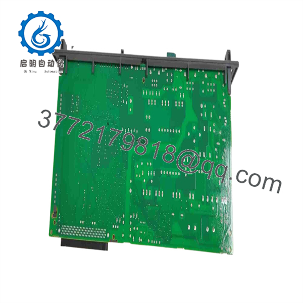
A16B-2203-0910
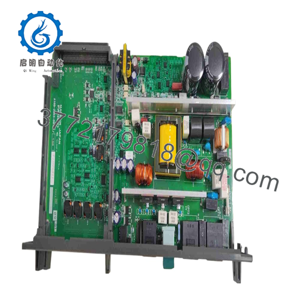
A16B-2203-0910
Installation & Configuration Guide
Stage 1 — Pre-Installation Preparation
- Confirm the complete part number A16B-2203-0910 on the existing power unit.
- Verify the robot controller model and hardware revision against the maintenance documentation.
- Shut down the robot and controller through the normal procedure.
- Apply lockout/tagout (LOTO) to the controller’s incoming power source.
- Allow the DC bus and internal power circuits to discharge for at least 5 minutes before opening the cabinet.
- Photograph the existing connector arrangement before removing any wiring.
- Prepare an ESD-safe work area and suitable grounding equipment.
- Retain the removed power unit until the replacement has passed commissioning.
Stage 2 — Removing the Existing Power Unit
- Verify that incoming AC power is absent with an appropriate meter.
- Remove the required controller cover or access panel.
- Identify CP1, CP1A, CP2/CP3, CP4, CP5, and CP6 as applicable to the installed configuration.
- Label wiring before disconnecting it.
- Disconnect the AC, control, and DC connections without pulling on the wires.
- Release the board/unit mounting hardware and remove the existing assembly.
- Inspect connectors, terminals, fuses, wiring insulation, and the surrounding controller PCB area for heat damage or contamination.
- Keep the failed unit available for comparison if the replacement has a different board revision.
The FANUC maintenance documentation identifies the power supply’s connectors and protection components, including the 8.0 A AC-input fuse and separate 7.5 A fuses for the +24 V and +24E circuits.
Stage 3 — Installing the Replacement
- Confirm that the replacement is A16B-2203-0910, including any suffix or board revision marked on the PCB.
- Inspect the PCB for bent pins, cracked components, corrosion, or shipping damage.
- Use ESD precautions when handling the board.
- Install the unit in the original mounting position.
- Reconnect each connector according to the controller maintenance documentation and your photographs.
- Do not modify the factory power-supply circuitry or add jumpers unless specifically required by the applicable FANUC manual.
- Check that no connector is partially seated.
- Verify that wiring is clear of fans, heat-producing components, and moving cabinet hardware.
The FANUC maintenance manual states that the A16B-2203-0910 power supply does not require setting or adjustment, so there is no normal field calibration procedure for this unit.
Stage 4 — Power-On & Testing
Before applying power:
- Verify AC input wiring and protective grounding.
- Check for accidental shorts between accessible DC rails and ground.
- Confirm connector seating.
- Confirm that downstream loads have no obvious wiring faults.
- Verify the correct controller configuration.
After energizing:
- Observe the power-supply status indicators.
- Confirm that the controller completes its normal startup sequence.
- Check the regulated rails against the FANUC specified tolerances.
- Confirm that controller alarms do not indicate a power-supply fault.
- Verify robot I/O and communications.
- Perform a controlled robot initialization and low-risk motion test.
- Return the system to production only after confirming normal operation.
The documented nominal rails are +5.1 V ±3%, +3.3 V ±3%, +2.5 V ±3%, +24 V ±5%, +24E +24 V ±5%, +15 V ±10%, and −15 V ±10%.
Common troubleshooting point: If the replacement immediately generates an alarm or fails to start, do not assume the power board is defective. Check incoming AC, downstream shorts, connector seating, fuse status, and the controller’s internal load first.
Frequently Asked Questions
Q1. What is FANUC ?
It is a FANUC power supply unit/power supply board used within legacy FANUC robot controller systems. Its function is to generate the multiple regulated DC rails required by the controller electronics.
Q2. Is only a 24 VDC power supply?
No. Although supplier listings often describe it as a 24 VDC / 200–240 VAC power supply, FANUC’s maintenance documentation shows that the unit provides several regulated rails: +5 V, +3.3 V, +2.5 V, +24 V, +24E, +15 V, and −15 V.
For that reason, replacing it with a generic 24 VDC power supply is not an equivalent substitution.
Q3. Which FANUC controllers use ?
Technical service and parts sources associate the unit with FANUC R-30iA and R-30iB controllers, with additional listings covering R-30iB Plus and R-J3iC configurations. Exact compatibility should be confirmed from the controller’s maintenance manual and the board revision before purchase.
Q4. Does require configuration or adjustment?
According to the FANUC R-30iB Controller Maintenance Manual, the power supply unit does not need to be set or adjusted.
Q5. Can /05A or /06A automatically replace ?
Do not assume that they are interchangeable solely because the base number is identical. The market contains variants with suffixes such as /05A and /06A, and those revisions should be checked against the exact controller hardware before substitution.
Q6. Is obsolete?
It should be treated as a legacy spare part for procurement planning. Current distributors and repair houses still list the part, while some specific revisions are explicitly marked discontinued. Availability therefore depends heavily on condition and revision.
For a critical production cell, it is advisable to record the exact board revision and maintain at least one tested spare rather than relying solely on spot-market availability.
Q7. What should be checked when purchasing a replacement?
Confirm all of the following before ordering:
- Exact part number:
- Board revision/suffix
- FANUC controller model
- Connector arrangement
- Physical PCB configuration
- AC input requirements
- Required regulated output rails
- Condition: new, surplus, refurbished, or repaired
- Functional test documentation for refurbished units
- Warranty and return terms
For obsolete FANUC hardware, part-number matching alone is not sufficient when multiple board revisions exist.



