
 WhatsApp: +86 16626708626
 Email:
  Phone: +86 16626708626
Description
Key Technical Specifications
| Parameter | Value |
|---|---|
| Manufacturer | Fairmount Automation |
| Model | PCM-1 |
| Product Family | Chameleon Process Control Module |
| Processor | 33 MHz ARM processor |
| Memory | 1 MB RAM, 1 MB Flash memory |
| Analog Inputs | 4 channels, minimum 16-bit resolution |
| Analog Input Signals | 0-20 mA, 4-20 mA, voltage, resistance, RTD |
| Analog Input Sampling Rate | Up to 1,000 Hz |
| Analog Outputs | 4 channels (2 × 14-bit, 2 × 10-bit resolution) |
| Digital Inputs | 2 opto-isolated inputs |
| Digital Output Type | 2 opto-isolated transistor outputs |
| Digital Input Frequency | Up to 500 kHz |
| Digital Output Frequency | Up to 50 kHz |
| Auxiliary Output | 24 VDC, maximum 250 mA |
| Power Consumption | 3.9 W + 0.03 W/mA auxiliary output load |
| Programming Interface | Fairmount Design Pad graphical programming software |
| Configuration Interface | 115 kbps SIR IrDA wireless interface |
| Operating Temperature | -40°C to +65°C |
| Storage Temperature | -40°C to +85°C |
| Shock Rating | MIL-STD-901D Grade A |
| Vibration Rating | MIL-STD-167B |
| EMI Rating | MIL-STD-461E |
| Enclosure Protection | NEMA 1, 2, 4X, 5, 6, 12, 12K, 13 |
| Dimensions | 4 in W × 6 in L × 3 in H |
| Weight | 2.1 lb |
Product Introduction
The Fairmount Automation PCM-1 is a Chameleon Process Control Module designed for multi-loop industrial control applications requiring analog, digital, and motor-control functions in harsh environments. It combines programmable control logic with integrated I/O, including 4 analog inputs, 4 analog outputs, 2 digital inputs, and 2 digital outputs.
The PCM-1 is commonly found in legacy marine, industrial, and process automation installations where sealed construction, EMI resistance, and configurable control logic are required. The module supports graphical programming through Fairmount Design Pad and remains available mainly through surplus inventory and repair channels due to lifecycle discontinuation.
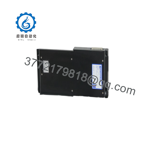
PCM-1
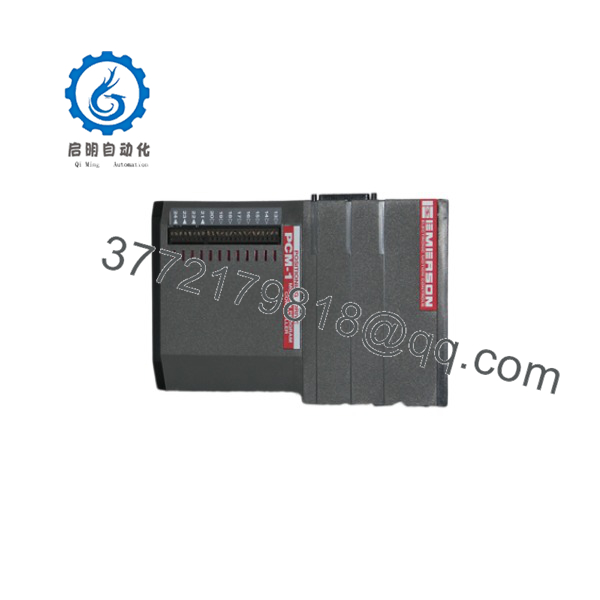
PCM-1
Installation & Configuration Guide
Stage 1: Pre-Installation Preparation (Estimated Time: 10 Minutes)
⚠️ Safety First
- Notify plant operations about the planned controller replacement.
- Place the controlled process into a safe operating condition.
- Apply lockout/tagout (LOTO) procedures before disconnecting wiring.
- Wait at least 5 minutes after power removal to allow capacitors to discharge.
Tools Required
- ESD wrist strap
- PH1 screwdriver
- Digital multimeter
- Wire labels
- Smartphone or camera for configuration records
Data Backup
- Save the existing PCM-1 control configuration from Fairmount Design Pad.
- Record the current application program version.
- Photograph:
- Terminal wiring
- Module labeling
- Any jumper settings
- External wiring routes
- Record connected I/O signal ranges:
- 4-20 mA loops
- RTD inputs
- Voltage signals
- Digital pulse inputs
Stage 2: Removing the Old Module (Estimated Time: 10 Minutes)
- Remove the PCM-1 front cover or enclosure access panel.
- Label every field connection before removal.
- Disconnect terminal wiring carefully. Do not pull cables by force.
- Release mounting hardware.
- Remove the module straight outward to avoid connector damage.
- Inspect:
- Terminal condition
- Connector pins
- Moisture contamination
- Corrosion marks
⚠️ Keep the original PCM-1 installed until the replacement is fully verified.
The old module provides the best reference for wiring and configuration recovery.
Stage 3: Installing the New Module (Estimated Time: 10 Minutes)
- Wear an ESD wrist strap before handling the replacement .
- Verify the replacement model matches the removed unit.
- Confirm enclosure style and wiring hub compatibility.
- Transfer wiring according to the original documentation.
Configuration Clone (Critical Step)
- Restore the original application program.
- Verify analog input ranges:
- 4-20 mA
- 0-10 V
- RTD type
- Resistance measurement range
- Confirm digital input modes:
- Pulse counting
- Frequency counting
- Quadrature decoding
Self Checklist
- Correct model installed
- Wiring labels verified
- Configuration restored
- Terminal connections tightened
- Enclosure sealing checked
Stage 4: Power-On & Testing (Estimated Time: 20 Minutes)
Pre-Power Check
- Measure supply voltage using a calibrated multimeter.
- Confirm no short circuit exists on the power terminals.
- Verify grounding connections.
Power-Up Sequence
- Energize the module.
- Observe status LEDs.
- Connect Fairmount Design Pad.
- Verify:
- Firmware information
- Application configuration
- I/O status
- Perform simulated input testing.
- Verify output response.
⚠️ Troubleshooting Note
- Incorrect analog readings usually indicate wrong input scaling.
- Failed communication may indicate configuration mismatch.
- Unexpected outputs often result from an incorrect restored control program.
Frequently Asked Questions (FAQ)
Q1: Is the Fairmount Automation still manufactured?
No. The is a legacy Chameleon product. Fairmount Automation announced the end of production for several legacy Chameleon modules, including active boards, due to component obsolescence. Existing units are typically sourced through surplus inventory, repair services, or replacement programs.
Q2: Is the a PLC or an I/O module?
The is more than a standard I/O module. It is a programmable process controller with its own ARM processor, memory, embedded firmware, and configurable I/O channels. It can execute control logic locally instead of relying only on a central PLC CPU.
Q3: Can I hot-swap a Fairmount ?
Yes, the design includes hot-swap capability according to Fairmount Automation documentation. However, site procedures should always be reviewed before performing live replacement. Marine and process environments often have additional safety requirements.
Q4: Will I lose my control program when replacing the ?
Not if the existing configuration has been backed up. The stores embedded firmware and application configuration in onboard memory. Before replacement, export the Design Pad configuration whenever possible.
Q5: What should I check before buying a replacement ?
Verify:
- Exact Fairmount part number
- Enclosure type
- Wiring hub compatibility
- Existing firmware/application compatibility
- Required I/O configuration
A with the wrong enclosure or wiring assembly can create unnecessary field modification work.
Q6: Why is inventory limited compared with newer PLC modules?
The belongs to the legacy Chameleon product family. Many installed systems remain operational, but replacement availability is limited because original production has ended. Engineers managing these systems should consider lifecycle planning and possible migration to newer Chameleon+ platforms.
Q7: What condition should I expect when purchasing a surplus ?
Available units may be:
- New Original / New Surplus: Unused OEM inventory stored in controlled conditions.
- Refurbished (tested): Previously installed units inspected, repaired if required, and function tested.
For critical control applications, request inspection records, test reports, firmware details, and actual product photos before purchase.



