
 WhatsApp: +86 16626708626
 Email:
  Phone: +86 16626708626
Description
Key Technical Specifications
| Parameter | Specification |
|---|---|
| Manufacturer | FANUC |
| Part Number | A06B-6107-H001 |
| Product Type | 6-axis servo amplifier |
| Series | A06B-6107 |
| Controller Family | R-J3iC / R-30iA |
| Number of Axes | 6 |
| Input Voltage | 200–240 V AC |
| Input Current | 32 A |
| Power Rating | 5.6 kW |
| Output | Servo motor power output |
| Application | FANUC robot motion control |
| Servo Amp Control PCB | A16B-3200-0610 |
| Servo Amp Power PCB | A20B-2101-0224 / A20B-2101-0234 |
| Approx. Weight | 7.7–15 kg, depending on listing and configuration |
FANUC aftermarket technical documentation consistently identifies A06B-6107-H001 as a six-axis servo amplifier/drive for R-J3iC and R-30iA controllers. One technical listing specifies 200–240 V AC input and 5.6 kW power, while another identifies a 32 A rating.
The associated board references are also documented as A16B-3200-0610 for the servo amplifier control circuit and A20B-2101-0224 / A20B-2101-0234 for the power circuit.
Product Introduction
The FANUC A06B-6107-H001 is a six-axis servo amplifier used in FANUC robot controllers to supply and regulate power to the robot’s servo motors. It belongs to the A06B-6107 series and is associated with the R-J3iC and R-30iA controller families. The published electrical data identifies a 200–240 V AC input and 5.6 kW power rating.
This is a motion-control power component, not a standalone robot controller. The exact amplifier configuration must be matched to the robot controller, servo motors, axis arrangement, and associated control/power boards. Secondary FANUC spare-parts references identify the H001 version as a six-axis drive and list A06B-6107-H001#B as a later replacement.
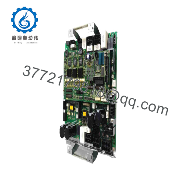
A06B-6107-H001
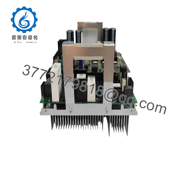
A06B-6107-H001
Installation & Configuration Guide
Stage 1 — Pre-Installation Preparation
- Confirm the complete part number: A06B-6107-H001.
- Verify the robot controller is an applicable R-J3iC or R-30iA configuration.
- Record the existing amplifier and robot controller part numbers.
- Back up robot programs, mastering data, servo parameters, and system configuration before maintenance.
- Apply the plant’s LOTO procedure.
- Disconnect the incoming servo power supply.
- Allow the DC bus and associated circuits to discharge for at least 5 minutes, or longer if required by the FANUC service procedure.
- Photograph and label power, control, and fiber-optic connections before removal.
Because this is a multi-axis high-power servo amplifier, verify the DC-bus discharge condition with the appropriate measurement procedure before touching power terminals.
Stage 2 — Removing the Existing Amplifier
- Place the robot controller in the approved maintenance state.
- Confirm incoming power is isolated.
- Verify that hazardous voltage has decayed to a safe level.
- Label motor output and feedback connections.
- Disconnect the control and communication connections.
- Disconnect the servo motor power connections.
- Remove the amplifier mounting hardware.
- Support the amplifier before removing the final mounting points.
- Inspect the cabinet, connectors, bus connections, cooling path, and wiring for heat damage or contamination.
Do not assume an amplifier fault is isolated to the amplifier. Overcurrent, ground-fault, or overtemperature conditions can originate from a motor, cable, mechanical load, or cabinet cooling problem.
Stage 3 — Installing A06B-6107-H001
- Verify the replacement part number and hardware configuration.
- Confirm the replacement is suitable for the existing six-axis system.
- Mount the amplifier in the original cabinet position.
- Secure all mounting hardware.
- Reconnect the servo motor power connections according to the original axis assignments.
- Reconnect encoder and control wiring.
- Reconnect the control-board and power-board interfaces.
- Verify the fiber-optic connections where applicable.
- Check grounding and cabinet bonding.
- Inspect all connections before applying power.
The is documented with an A16B-3200-0610 control circuit board and A20B-2101-series power circuit boards. If replacing an incomplete assembly, confirm that the board configuration matches the original amplifier before installation.
Stage 4 — Power-On & Testing
After installation:
- Verify all axis motor connections.
- Check incoming voltage before enabling servo power.
- Power the controller according to the FANUC service procedure.
- Check amplifier status and alarm indicators.
- Confirm the controller recognizes the six-axis amplifier.
- Check for servo amplifier alarms.
- Verify encoder feedback for each axis.
- Perform controlled servo-on testing.
- Jog each axis at low speed.
- Check motor direction and axis position.
- Verify abnormal current, vibration, or following-error conditions.
- Perform a controlled production-cycle test before returning the robot to normal operation.
Critical Replacement Checks
Controller compatibility: is associated with R-J3iC and R-30iA systems. A physically similar FANUC amplifier from another generation should not be treated as a direct substitute.
Six-axis configuration: The H001 is identified as a 6-axis servo drive. Confirm that the replacement matches the original axis allocation and robot configuration.
Electrical rating: Published listings identify 200–240 V AC, 32 A, and 5.6 kW. Verify the nameplate and controller documentation before energizing the replacement.
Replacement suffix: Secondary FANUC parts references identify as a replacement for the version. Treat the #B suffix as a specific replacement configuration, not merely a cosmetic revision, and verify compatibility before substitution.
Frequently Asked Questions (FAQ)
1. A?
is a six-axis FANUC servo amplifier/servo drive used in FANUC robot motion-control systems. It is associated with R-J3iC and R-30iA controller configurations.
2. Whatd use?
Available technical listings specify a 200–240 V AC input. One listing also identifies a 32 A rating and 5.6 kW power rating. Verify the actual nameplate and controller documentation before installation.
3. How many axes does this servo amplifier control?
The is identified as a 6-axis servo drive. Its application includes FANUC robot systems requiring six servo axes.
4. Which FANUC co ?
Technical parts listings identify the for FANUC R-J3iC and R-30iA controllers. Specific robot compatibility should still be verified against the robot model and controller configuration.
. Is discontinued?
Yes. Radwell identifies the original as discontinued by the manufacturer and lists as its replacement. Legacy units remain available through the industrial aftermarket in new-old-stock, used, refurbished, and repair channels.
Can #B directeplace H001?
The #B version is identified by secondary FANUC parts references as the replacement for , but replacement should still be checked against the robot controller’s hardware configuration, wiring, firmware/system configuration, and associated servo components.
7. What should be verified before purchasing?
For a FANUC robot maintenance replacement, verify:
- exact part number
- Six-axis configuration
- 200–240 V AC input
- 32 A rating
- 5.6 kW power rating
- R-J3iC / R-30iA compatibility
- Existing control and power board configuration
- Servo motor and encoder connections
- Hardware revision
- versus #B identification
- New, unused, used, or refurbished condition
- Functional test documentation and warranty
For a legacy FANUC controller, the safest procurement method is to match the complete amplifier part number and the controller/robot configuration, rather than selecting a drive solely by voltage or physical dimensions.



