
 WhatsApp: +86 16626708626
 Email:
  Phone: +86 16626708626
Description
Key Technical Specifications
| Parameter | Specification |
| Manufacturer | FANUC Corporation |
| Part Number | A06B-6130-H002 |
| Product Line | Beta iSV Series (Single Axis) |
| Nominal Input Voltage | 283–325 VDC |
| Maximum Output Voltage | 240 VAC |
| Rated Output Current | 13 A |
| Peak Output Current | 40 A |
| Control Interface | FSSB (FANUC Serial Servo Bus) / High-Speed Serial |
| Cooling Method | Natural convection / Heat sink air flow |
| Operating Temperature | 0 to 55 °C |
| Enclosure Rating | IP20 |
| Weight | Approx. 1.8 kg (3.97 lbs) |
Product Introduction & Supply Chain Strategy
The FANUC A06B-6130-H002 is a single-axis Beta iSV series servo amplifier engineered for high-precision speed and position control in CNC machine tools. It directly drives Beta series AC servo motors, converting DC bus voltage into precise three-phase power output based on real-time feedback from optical encoders. Commonly integrated into milling machines, lathes, and specialized automation cells, this drive delivers reliable power conversion while maintaining tight motion synchronization with the CNC main controller.
From a supply chain perspective, stocking this drive as New Surplus mitigates severe financial exposure during unexpected line stops. Refurbished drives frequently contain degraded DC bus capacitors and thermally stressed power modules that lead to premature gate-driver failure under heavy machining loads. Buying New Surplus guarantees factory-grade silicon and full dielectric strength, lowering your Total Cost of Ownership (TCO) by avoiding the 10,000 to 50,000 per hour losses typical of unplanned production shutdowns.
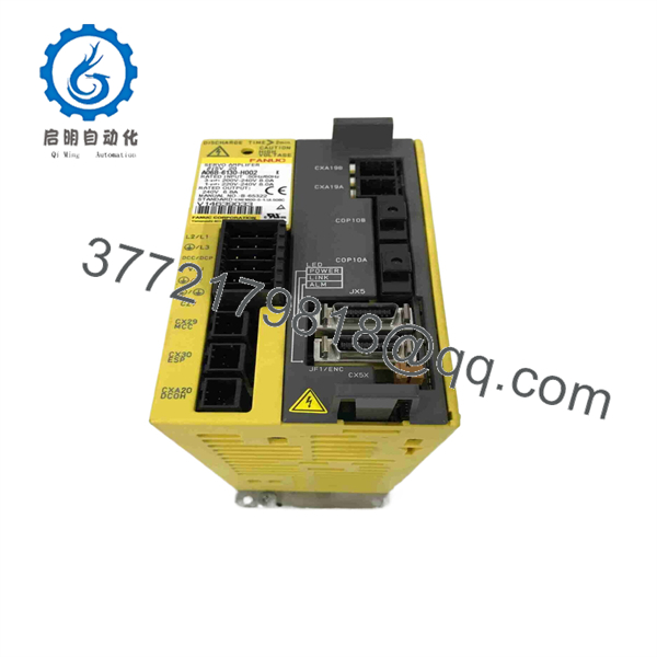
A06B-6130-H002
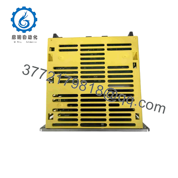
A06B-6130-H002
Installation & Configuration Guide
1.Stage 1: Pre-Installation (Prep & Safety):Ensure main power isolate and LOTO compliance.
Disconnect all incoming 3-phase AC power to the enclosure and apply Lock-Out/Tag-Out (LOTO) procedures. Wait a minimum of 10 minutes to allow the internal DC bus capacitors to fully discharge. Verify zero voltage across the DC bus terminals using a calibrated multimeter before touching any wiring. Wear a grounded wrist strap to prevent ESD damage to the internal logic boards. Photograph all cabling, terminal connections, and DIP switch locations prior to disconnecting.
2.Stage 2: Removal:Protect backplane and connector pin integrity.
Unscrew the cable retaining clamps and disconnect the FSSB optical fiber/communication connectors, power terminals, and motor feedback cables. Unscrew the top and bottom mounting bolts securing the A06B-6130-H002 chassis to the mounting panel. Carefully lift the unit straight out to prevent bending or scratching the rear heat sink or adjacent wiring channels.
3.Stage 3: Installation (Clone & Seat):Replicate settings and torque connections to spec.
Inspect the mounting surface and clean off any debris or metal dust. Verify that the DIP switch settings and hardware jumpers on the new A06B-6130-H002 match the original unit exactly. Position the drive onto the backplate mounting studs and tighten the mounting screws securely to maintain proper grounding contact. Reconnect the DC bus power lines, motor phase leads (U, V, W), and control harnesses using the photos taken during removal.
4.Stage 4: Power-On & Testing:Perform cold checks before high-voltage energization.
Execute a continuity check between power phases and ground to rule out short circuits. Apply logic power first and observe the single-digit LED display on the front panel. Confirm that no alarm status (such as Alarm 2, 8, or b) appears. Download or verify the machine axis parameters from the CNC controller. Energize the high-voltage DC bus and execute low-speed jog commands to confirm smooth motor rotation and proper encoder feedback tracking.
Firmware/Software Versions & Upgrade Notes
- Recommended Firmware Baseline: The A06B-6130-H002 utilizes embedded bootware designed for seamless handshake protocols with FANUC 0i-MC, 0i-MD, 18i-MB, and 21i-MB control systems running standard FSSB servo software.
- Backward & Forward Compatibility: Software options inside the CNC controller dictate parameter recognition. Swapping this module across different CNC generations requires matching the Servo ID parameters in the controller setup screen. Upgrading controller software without updating servo parameters can cause communication timeouts (e.g., FSSB initialization error Alarms 5136–5138).
- Firmware Risk Warning: Never attempt field firmware flashes on this drive unless guided directly by FANUC field engineers. Flash failures on the main control PCB render the unit unbootable, requiring factory-level bench restoration.
Frequently Asked Questions (FAQ)
Q: Why is this unit priced higher than refurbished options online, but lower than direct OEM list price?
A: This product is a Brand New Surplus unit. It is not used, not pulled from a decommissioned plant, and not refurbished. All modules undergo rigorous quality verification to ensure OEM-level reliability. Refurbished units carry hidden degradation risks in their electrolytic capacitors and power IGBTs. Our pricing reflects the cost of sourcing genuine, unused global inventory, giving you 100% operational reliability at a lower cost than direct OEM list prices.
Q: Is the FANUC A06B-6130-H002 fully obsolete, and how should we manage stock for it?
A: FANUC has transitioned newer machine designs to the Beta iSV-B series. However, millions of installed CNC axes still rely on the original . Because factories cannot easily upgrade the entire CNC architecture, we recommend maintaining 1 to 2 New Surplus units on-site as critical safety stock to eliminate long lead times during a drive failure.
Q: Can I hot-swap this servo amplifier while the CNC cabinet is powered?
A: No. Attempting to hot-swap the will cause severe electrical arcing across the DC bus terminals, immediate destruction of the internal gate circuitry, and potential damage to the FSSB optical transceiver in the main CNC controller. Always de-energize the entire cabinet before swapping hardware.
Q: Does this drive hold axis position parameters when powered off?
A: The amplifier processes encoder signals, but absolute position data is retained via the pulse coder battery backup circuit connected to the motor/drive feedback harness. If replacing a drive on an absolute encoder axis, you may need to reset the reference point (grid position / zero point) via CNC parameter 1815 once the new drive is installed.
Q: What warranty and authenticity verification do you provide with this module?
A: Every ships in anti-static protective packaging with verifiable OEM serial numbers and an accompanying QC Test Report covering power-on handshake and I/O validation. We back this New Surplus module with a comprehensive 1-year replacement warranty.



