
 WhatsApp: +86 16626708626
 Email:
  Phone: +86 16626708626
Description
Key Technical Specifications
| Parameter | Specification |
|---|---|
| Manufacturer | FANUC |
| Part Number | A20B-2001-0065/06A |
| Base Board Number | A20B-2001-0065 |
| Board Type | Master P.C.B. / CNC control board |
| CNC Generation | FANUC Series 0-C, 32-bit |
| CPU | High-speed CPU architecture |
| Control Architecture | Split master-board architecture |
| Supported Series | 0-C / 0-MC / 0-TC / 0-TTC / 0-TF / 0-MF |
| Axis Configuration | Up to 8 axes, depending on system configuration |
| Memory Function | Stores CNC system memory, programs, parameters, and ladder-related data |
| I/O Configurations | 40/40, 80/56, or 104/72 configurations are documented for the board family |
| PMC Support | PMC-L or independent PMC-M configurations |
| Servo Architecture | Supports systems using serial-interfaced FANUC AC spindle drives and FANUC Alpha spindle drives |
| CPU Generation | 32-bit high-speed generation |
| Status | Legacy / discontinued |
FANUC maintenance documentation identifies A20B-2001-0065 as the high-speed-CPU version of the Series 0-C Control Section B master PCB, replacing the conventional A20B-2001-0060 version.
The /06A designation is used in current spare-parts listings for this master-board assembly. Because the available FANUC documentation generally identifies the base board as A20B-2001-0065, the suffix should be matched against the physical board and machine documentation before substitution.
Product Introduction
The FANUC A20B-2001-0065/06A is a Series 0-C CNC master PCB built around FANUC’s 32-bit high-speed control architecture. It functions as the principal processing board in the control system, working with peripheral PCBs for memory, I/O, PMC, axis control, and other CNC functions. FANUC documentation specifically lists A20B-2001-0065 as the high-speed-CPU version of the Series 0-C Control Section B board.
This is not a generic PLC CPU or interchangeable industrial motherboard. The board is tied to the FANUC Series 0-C hardware architecture, software generation, peripheral boards, and machine configuration. Before replacing one, confirm the complete board number, /06A revision, CNC model, installed peripheral cards, memory configuration, and stored machine data. Independent technical sources also identify the as a 0-C master board / 32-bit high-speed CPU board.
Installation & Configuration Guide
Stage 1 — Pre-Installation Preparation
- Record the machine’s complete FANUC control model and CNC software version.
- Photograph the existing board, connectors, jumpers, daughterboards, and memory devices.
- Record machine parameters, PMC ladder data, CNC programs, offsets, and other configuration data before removing the board.
- Shut down the CNC through the normal machine procedure.
- Apply lockout/tagout (LOTO) to the machine’s electrical supply.
- Wait at least 5 minutes after power removal before accessing the control cabinet.
- Verify that hazardous voltage has been removed with an appropriate meter.
- Use ESD protection when handling the PCB.
- Keep the original board until the replacement has been fully commissioned.
For this generation of FANUC control, data preservation is particularly important. The master PCB is part of the CNC control architecture rather than merely an I/O interface, so replacing it can affect stored control data and system configuration.
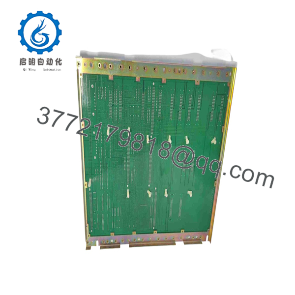
A20B-2001-006506A
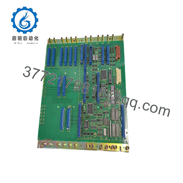
A20B-2001-006506A
Stage 2 — Removing the Existing Master PCB
- Confirm that the incoming electrical supply is isolated.
- Open the CNC control cabinet according to the machine builder’s service procedure.
- Identify the existing board by its complete part number and revision.
- Label connectors before disconnecting them.
- Photograph connector orientation and cable routing.
- Carefully disconnect the board from the backplane and associated wiring.
- Remove the PCB mounting hardware.
- Inspect the backplane connectors for oxidation, contamination, bent contacts, or mechanical damage.
- Inspect adjacent boards for signs of overheating or failed components.
- Place the removed board in an ESD-safe bag.
Do not assume that a visually identical board is interchangeable. The FANUC maintenance documentation distinguishes tigh-speed from the conventional -2001-0060 Control Section B board.
Stage 3 — Installing the Replacement
- Verify against the original board.
- Check PCB revision markings and installed memory components.
- Inspect the replacement PCB for corrosion, damaged connectors, cracked components, or contamination.
- Transfer configuration-dependent components only when the applicable FANUC documentation explicitly requires it.
- Install the PCB without forcing the edge connector or mounting hardware.
- Reconnect all cables according to the original documentation and photographs.
- Verify that every connector is fully seated.
- Check the board for loose screws, foreign objects, or cable interference.
- Close the cabinet sufficiently to prevent accidental contact before initial energization.
Critical compatibility check
The Series 0-C architecture uses multiple boards to divide processing, memory, I/O, and axis-control functions. One technical description iifies the as supporting 5th through 8th serial servo axes through associated processing hardware, with PMC-L or independent PMC-M configurations and several I/O arrangements.
Therefore, do not select the replacement solely by physical dimensions or the base number.
Stage 4 — Power-On & Testing
After installation:
- Perform a visual inspection before applying power.
- Verify cabinet grounding and incoming supply wiring.
- Energize the CNC under controlled conditions.
- Observe the initial CNC display and diagnostic indications.
- Check for CPU, memory, PMC, I/O, servo, or system alarms.
- Verify that the CNC software/version is appropriate for the replacement hardware.
- Restore or verify machine parameters and PMC data as required.
- Confirm CNC I/O operation.
- Check servo amplifier communication and axis feedback.
- Verify spindle communication and operation where applicable.
- Perform controlled manual-axis movement.
- Execute a low-risk dry run before returning the machine to production.
Typical troubleshooting sequence
If the control fails to boot after replacement, check these items in order:
- Board part number and
/06Arevision - Board seating and connector engagement
- Memory and configuration data
- CNC software compatibility
- Backplane condition
- PMC configuration
- Servo/axis peripheral-board compatibility
- Existing power-supply or cabinet wiring faults
A replacement master PCB can be perfectly functional and still fail to bring a machine into service if the stored configuration, software generation, or peripheral-board combination does not match.
Frequently Asked Questions
Q1. is FANUC /06A?
It is a FANUC Series 0-C 32-bit high-speed master PCB used as a central processing/control board in legacy FANUC CNC systems. FANUC maintenance documentation l the base as the high-speed-CPU version of the Series 0-C Control Section B board.
Q2. Which FANUCtrols use ?
The documented Series 0-C applications include 0-TC, 0-TF, 0-TTC, 0-MC, 0-MF, 0-GSC, and 0-GCC configurations. The exact application depends on the complete control architecture and software configuration.
Q3. Is the sameA20B-2001-0060?
No. FANUC maintenance documentatidentifies as the high-speed CPU version and -2001-0060 as the conventional version. They should not be treated as automatic substitutes.
Q4. What does the /06A suffix mean?
The market identifies as a specific revision/configuon of the master board. However, the primary FANUC maintenance material located for this board generally identifies the base number rather than providing a detailed /06A revision matrix. Therefore, the /06A marking should be verified directly from the existing PCB and machine documentation before ordering.
Q5. Can this board be used in a newer FANUC 0i, 16i, or 18i CNC?
Do not assume compatibility. Some aftermarket listings incorrectly or ely group /06A with later FANUC control families. The stronger technical documenon places in the Series 0-C 32-bit architecture.
Q6. Is obsolete?
Yes. Current industrial spare-parts sourcesntify the as discontinued by the manufacturer, although new-old-stock, used, refurbished, and repair/exchange units remain available through specialist suppliers.
Q7. What should be checked before purchasing a replacement?
At minimum, verify:
- Complete part number:
- PCB revision
- FANUC Series 0-C control model
- CNC software generation
- Existing memory configuration
- PMC-L/PMC-M arrangement
- I/O configuration
- Servo-axis configuration
- Spindle interface
- Connector and backplane arrangement
- Condition: new old stock, used, refurbished, or repaired
- Functional test documentation
- Warranty and return terms
For a legacy Series 0-C machine, preserving the original board and machine data until the replacement has been fully tested is a prudent maintenance practice. Specialist repair suppliers specifically offer testing, repair, and exchange services for this board because of its legacy status.



