
 WhatsApp: +86 16626708626
 Email:
  Phone: +86 16626708626
Description
Key Technical Specifications
| Parameter | Specification |
| Manufacturer | FANUC Corporation |
| Part Number | A20B-3400-0020 |
| Control System Compatibility | FANUC Series 30i-A, 31i-A, 32i-A |
| Board Type | Sub CPU / High-Speed Auxiliary Processor |
| Power Supply Input | 24 VDC (via main board bus interface) |
| Mounting Style | Plug-in Daughterboard (Main CPU Rack Mount) |
| Bus Interface | High-Speed Proprietary FANUC System Bus |
| Operating Temperature | 0 to 55 °C |
| Storage Temperature | −20 to 60 °C |
| Humidity Rating | 10 to 90% RH (non-condensing) |
| Weight | Approx. 0.35 kg (0.77 lbs) |
Product Introduction & Supply Chain Strategy
The FANUC A20B-3400-0020 is a high-speed Sub CPU board designed to expand the computing capacity of FANUC Series 30i, 31i, and 32i Model A CNC systems. Installed as an auxiliary coprocessor card onto the main control PCB, this board offloads intensive calculation tasks such as multi-path execution, 5-axis surface machining interpolation, and advanced look-ahead motion algorithms. It ensures real-time servo loop processing without degrading the primary PMC or main CPU cycle times.
From a supply chain standpoint, maintaining an A20B-3400-0020 as New Surplus prevents severe operational bottlenecks in complex machining centers. Refurbished option boards often harbor latent thermal stress in multi-layer logic traces and surface-mount components, resulting in intermittent bus communication errors and random machine freezes under peak processor loads. Purchasing New Surplus guarantees factory-grade silicon and pristine connector contacts, reducing your Total Cost of Ownership (TCO) by protecting high-value CNC production lines against unexpected multi-day stoppages.
Installation & Configuration Guide
1.Stage 1: Pre-Installation (Prep & Safety):Perform full system backup and enforce LOTO safety.
Back up all CNC parameters, PMC programs, system settings, and custom macro variables to a flash card before shutting down the machine. Turn off main power to the CNC cabinet and execute Lock-Out/Tag-Out (LOTO) procedures. Wait 10 minutes to allow all power supplies to discharge completely. Attach a grounded ESD wrist strap before handling electronic cards. Take detailed reference photos of the main CPU rack and the existing daughterboard mounting arrangement.
2.Stage 2: Removal:Remove main CPU assembly and detach sub board.
Disconnect external communications and interface cabling connected to the main control board. Unlatch and pull the main CPU assembly straight out along its guide rails to access the option card slots. Carefully loosen the retaining screws or plastic standoffs securing the old A20B-3400-0020 to the main board. Lift the board straight up to disengage its pin connectors without bending or stressing the interconnect pins.
3.Stage 3: Installation (Clone & Seat):Align connectors and seat card onto main board.
Inspect the board connectors and mounting points for dust or debris. Align the pin headers of the new A20B-3400-0020 with the mating socket on the main CPU PCB. Press down evenly on both ends of the card until the connectors are fully seated and locking standoffs engage. Tighten all securing screws to manufacturer torque specs to ensure stable mechanical grounding. Re-insert the main CPU assembly into the rack.
4.Stage 4: Power-On & Testing:Verify power rails and confirm option recognition.
Reconnect all control cables and restore cabinet power. Apply 24 VDC logic power and monitor the front-panel status LEDs and 7-segment display for normal boot sequence. Access the CNC system diagnostic/status screens to verify that the Sub CPU option is recognized and functioning without bus alarm errors (e.g., System Alarm or Option Board Communication Error). Test high-speed motion routines in dry-run mode to confirm stable processing.
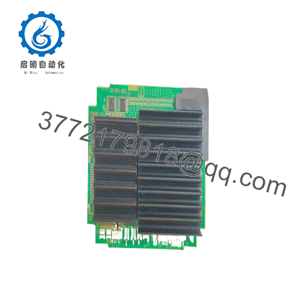
A20B-3400-0020
Firmware/Software Versions & Upgrade Notes
- Bootware & Option Compatibility: The A20B-3400-0020 hardware operates under firmware managed by the main CPU system software. Ensure the main system software version supports the specific Sub CPU functionality required for your machine’s option parameters.
- Hardware Revision Matching: Revision variations (such as /01A, /02B) generally maintain backward interface compatibility. However, ensure that jumper settings or hardware revisions on the new board match your original unit to prevent system initialization faults.
- Firmware Mismatch Risk Warning: Replacing a Sub CPU card with an incompatible hardware revision without verifying CNC system software readiness can lead to startup loops, unrecognized option errors, and system bus timeouts.
Frequently Asked Questions (FAQ)
Q: Why is this unit priced higher than refurbished options online, but lower than direct OEM list price?
A: This product is a Brand New Surplus unit. It is not used, not pulled from a decommissioned plant, and not refurbished. All modules undergo rigorous quality verification to ensure OEM-level reliability. Refurbished option PCBs often suffer from hidden micro-cracks and thermal fatigue in BGA chips. Our pricing reflects unused, original global inventory offered at a significant savings over direct OEM list price.
Q: Is the FANUC obsolete, and why should we stock it?
A: While FANUC has migrated newer machine lines to Model B and C series hardware, thousands of active Series 30i/31i/32i Model A controls remain in daily production. Because this Sub CPU handles specialized high-speed or multi-path processing, a failure will halt the entire machine. Keeping 1 unit in critical spare stock eliminates long lead times and avoids costly production delays.
Q: Will installing a new wipe my CNC parameter memory?
A: Installing the Sub CPU board itself does not clear SRAM parameter memory, as parameters reside on memory modules attached to the main board. However, improper handling or static discharge during the swap can corrupt data. Always perform a complete system backup before installing or removing any option card.
Q: Can I plug in or remove this Sub CPU board while the CNC rack is powered on?
A: No. Hot-plugging any daughterboard on a FANUC CNC main board will cause high-current voltage spikes across the system bus, permanently damaging driver ICs on both the Sub CPU and the main control motherboard. Always turn off power and wait for complete discharge.
Q: What warranty and quality verification do you provide with this module?
A: Every is shipped in anti-static ESD shielding bags with verifiable OEM serial numbers and an accompanying QC Test Report covering pin continuity and power-on bus checks. We back this New Surplus module with a 1-year replacement warranty.



