
 WhatsApp: +86 16626708626
 Email:
  Phone: +86 16626708626
Description
Key Technical Specifications
| Parameter | Specification |
|---|---|
| Manufacturer | FANUC |
| Part Number | A860-2005-T505 |
| Product Type | Encoder connection cable |
| Function | Servo encoder / pulse-coder feedback transmission |
| Application | FANUC CNC and servo motor systems |
| Signal Category | Encoder feedback |
| Related FANUC Cable | A660-2005-T505 |
| Related Encoder Family | A860-series pulse coders |
| Connector Configuration | FANUC-specific; verify against installed equipment |
| Cable Length | Configuration-dependent; do not assume a length from the part number alone |
| Installation | Servo motor encoder to compatible FANUC control/drive interface |
| Condition | New, used, or replacement cable depending on source |
Exact technical information for A860-2005-T505 is limited in publicly available primary documentation. Multiple industrial suppliers consistently classify it as an encoder connection/feedback cable, while the closely related A660-2005-T505 is documented as a FANUC encoder feedback cable.
One important procurement point is that suppliers sometimes group A860-2005-T505 with A660-series cable numbers or use the two designations interchangeably in listings. That does not establish electrical or mechanical interchangeability. The complete original cable marking and mating connector arrangement should be checked before substitution.
Product Introduction
The FANUC A860-2005-T505 is a servo encoder connection cable used to carry feedback signals between a FANUC servo motor’s encoder/pulse coder and the associated CNC or servo-control hardware. Accurate feedback transmission is essential for the controller to determine motor position and speed in a closed-loop servo system. Industrial parts catalogs specifically list this model as a FANUC encoder connection line.
This is a cable assembly, not an encoder. That distinction matters when troubleshooting. An encoder alarm can originate from the pulse coder, cable, connector, shielding, controller input, or associated drive hardware. Replacing the A860-2005-T505 is appropriate only after confirming that the cable or its connections are the likely fault source.
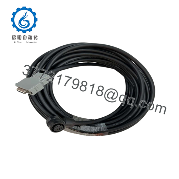
A860-2005-T505
Installation & Configuration Guide
Stage 1 — Pre-Installation Preparation
- Record the complete cable marking: A860-2005-T505.
- Record the FANUC servo motor model and complete A06B motor ordering number.
- Record the associated CNC/controller and servo amplifier model.
- Photograph both cable ends and connector orientation.
- Record the existing cable routing and approximate installed length.
- Shut down the machine through the normal CNC procedure.
- Apply lockout/tagout (LOTO) to the machine’s electrical supply.
- Wait at least 5 minutes after power removal before accessing the servo cabinet.
- Verify that hazardous voltage has been removed.
- Use ESD precautions around the encoder and CNC interfaces.
Do not order a replacement based only on the fact that it is described as a “FANUC encoder cable.” FANUC uses multiple A860/A660 cable families with different encoder and connector configurations.
Stage 2 — Removing the Existing Cable
- Confirm that the servo amplifier and motor are de-energized.
- Identify the motor-side encoder/pulse-coder connector.
- Identify the controller/drive-side connector.
- Label both ends before disconnection.
- Disconnect the connectors without pulling on the cable.
- Inspect connector pins and locking mechanisms.
- Remove the cable from its clamps and cable track.
- Inspect the complete cable for cuts, crushed sections, oil contamination, abrasion, or excessive bending.
- Check the connector backshells for mechanical damage.
A cable that has been repeatedly flexed, pinched, or routed near a high-current motor cable can produce intermittent encoder faults even when its insulation appears intact.
Stage 3 — Installing the Replacement
- Confirm the replacement marking is .
- Compare both connectors with the removed cable.
- Verify the cable length is adequate for the machine’s existing routing.
- Connect the motor-side encoder connector.
- Connect the controller/drive-side connector.
- Confirm both locking mechanisms are fully engaged.
- Route the cable along the original cable path.
- Maintain appropriate separation from high-current motor-power conductors where the machine design requires it.
- Avoid sharp bends, crushing, excessive tension, and unsupported cable weight at the connectors.
- Restore cable clamps and strain relief.
Critical compatibility check
The A660-2005-T505 is commonly described as a 15 m encoder feedback cable and is also associated with certain A860 pulse-coder applications. However, the existence of similar T505 designations does not by itself prove that and A660-2005-T505 are direct substitutes.
Match:
- Motor model
- Pulse-coder model
- Controller/servo amplifier
- Cable part number
- Connector type
- Connector orientation
- Cable length
- Machine cable routing
Stage 4 — Power-On & Testing
- Inspect the completed cable installation.
- Verify that connectors are fully locked.
- Confirm that the cable is not under mechanical tension.
- Restore machine power.
- Clear only the alarms that are appropriate to clear after the repair.
- Check for encoder/pulse-coder communication alarms.
- Verify the CNC recognizes the servo axis correctly.
- Perform the machine’s required reference/zero-return procedure.
- Jog the axis at low speed.
- Check position feedback for stable operation.
- Perform repeated low-speed movements.
- Run a controlled production-equivalent test cycle.
Troubleshooting sequence
If an encoder alarm remains after cable replacement, check:
- Encoder/pulse-coder condition
- Cable connector seating
- Connector pin damage
- Cable continuity
- Cable shielding/grounding
- Motor-side connector
- CNC/servo amplifier feedback input
- Servo amplifier alarm history
- Absolute-position battery condition where applicable
- Motor and pulse-coder compatibility
Do not repeatedly replace cables if the same encoder alarm returns. An intermittent feedback fault can originate in the pulse coder or controller input rather than the cable itself.
Frequently Asked Questions
Q1. What is FANUC ?
It is a FANUC encoder connection/feedback cable used with compatible FANUC servo motor and CNC feedback systems. It carries encoder or pulse-coder feedback signals between the motor and control hardware.
Q2. Is an encoder?
No. , not the pulse coder itself. FANUC uses separate part numbers for pulse coders and encoders, such as -2000-T301 and -2005-T301.
Q3. Is the same as A660-2005-T505?
They are closely related FANUC encoder-cable designations, and suppliers frequently list them together. However, they should not automatically be treated as interchangeable. Verify the complete motor, encoder, controller, connector, and cable configuration before substitution.
Q4. What does an encoder cable failure look like?
Typical symptoms can include encoder communication alarms, servo-axis faults, unstable position feedback, failure to complete reference return, intermittent servo errors, or an axis that cannot be enabled.
Before replacing the cable, inspect both connectors and check cable continuity. Cable damage is particularly likely when the cable runs through a moving cable carrier or has been exposed to repeated bending.
Q5. Can a generic encoder e replace ?
Not as a direct assumption. FANUC feedback systems can require specific connector pinouts, shielding, conductor arrangements, and signal characteristics. A generic cable should only be considered after its complete electrical and mechanical interface has been verified against the FANUC system.
Q6. What should be checked befourchasing ?
Confirm:
- Exact part number:
- FANUC servo motor model
- Complete pulse-coder/encoder part number
- CNC/controller model
- Servo amplifier model
- Connector type and orientation
- Cable length
- Cable routing requirements
- New versus used/refurbished condition
- Continuity and insulation test results where available
- Supplier warranty and return terms
Q7. Is still available?
It is a legacy FANUC spare-part number and remains listed by specialist industrial automation suppliers, although availability and condition vary. Current listings include new and replacement cable assemblies, while related A660-2005-T505 cables are also available in the aftermarket.
For a production-critical FANUC axis, retain the original cable until the replacement has been installed and the axis has completed a full feedback and motion test.



