
 WhatsApp: +86 16626708626
 Email:
  Phone: +86 16626708626
Description
Key Technical Specifications
| Parameter | Value |
|---|---|
| Manufacturer | Fife Corporation |
| Model | CDP-01-MH |
| Product Family | CDP-01 |
| Product Type | Web Guide Control Assembly / Signal Amplifier |
| Primary Application | Moving sensor center guide |
| Input Supply | 120 VAC class configuration |
| Nominal Frequency | 50/60 Hz |
| Maximum Motor Output | 80 W |
| Control Modes | Manual / Automatic |
| Guiding Modes | Edge guiding / center guiding |
| Sensor Arrangement | Moving sensor with fixed web center point |
| Application Variant | MH — moving-sensor / armless-recoiler configuration |
| Drive Configuration | Drive 1 for sensor positioner; Drive 2 for mandrel in the documented MH recoiler configuration |
| Software Identification | Matrix Setup No. + State Machine No. + firmware revision |
| Historical Firmware Requirement | Firmware version ≥ 2.0 for the documented moving-sensor application |
| Historical D1 Software | 565023-02x |
| Historical D2 Software | 565024-02x |
| Historical MH Matrix Setup | 581035.02x |
| Historical MH State Machine | 581036.02x |
The original Fife supplementary manual identifies the CDP-01-MH software configuration as MS 581035.02x / SM 581036.02x, with D1/D2 software part numbers 565023-02x and 565024-02x. It also states that signal amplifiers with firmware version 2.0 or later were required for that documented application.
For the armless-recoiler configuration, the manual states that CDP-01-MH uses drive 1 for the sensor positioner and drive 2 for the mandrel, while the mandrel-to-sensor-positioner ratio is programmable.
Important specification caution: Available secondary listings disagree on some electrical details, including input-voltage presentation and weight. One listing identifies the unit as 120 VAC, while another describes a 90–122 VAC range and 6.1 kg weight. The original documentation should take precedence over aftermarket listings for a particular unit.
Product Introduction
The Fife CDP-01-MH is a CDP-01 web-guide control assembly designed for moving-sensor guiding applications. It processes sensor and position feedback and controls the associated guide/actuator system to maintain the required web position. Fife documentation also identifies the MH variant for armless recoiler applications with programmable sensor-positioner-to-mandrel ratio control.
This is a configuration-sensitive legacy controller. Its software identity includes Matrix Setup, State Machine, and firmware information, so a physically identical replacement may not have the same application configuration. Record the complete software identification from the original unit before ordering.
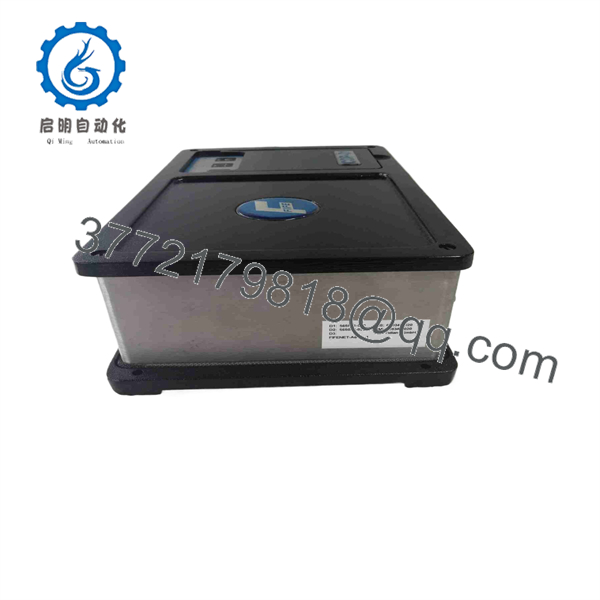
CDP-01-MH
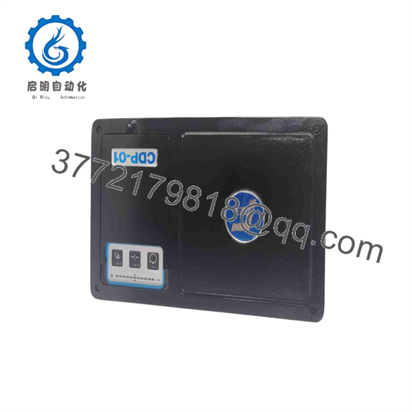
CDP-01-MH
Installation & Configuration Guide
Stage 1: Pre-Installation Preparation — Approximately 10 Minutes
⚠️ Safety First: The CDP-01-MH is an AC-powered web-guide controller connected to motors and/or actuators. Stop the web line, place the machine in a safe maintenance state, isolate the power source, and follow the site’s lockout/tagout procedure before opening or removing the controller.
Tools Required:
- ESD wrist strap
- Insulated screwdriver set
- Digital multimeter
- Wire labels
- Smartphone or camera
- Current Fife wiring diagram
- Original -MH documentation
- Replacement-unit identification label
Data Backup
- Record the te nameplate information.
- Photograph the front panel and all external connectors.
- Photograph every terminal and cable before disconnecting anything.
- Record the Matrix Setup number.
- Record the State Machine number.
- Record the firmware/software revision.
- Record sensor-position feedback connections.
- Record guide and mandrel drive connections.
- Record motor/actuator polarity.
- Record the existing calibration values.
⚠️ Do not order a replacement solem “.” Fife’s documentation explicitly states that the software part numbers are application-specific and should be quoted when making inquiries.
Stage 2: Removing the Old Controller — Approximately 5–10 Minutes
- Confirm that AC power has been isolated.
- Verify absence of voltage with an appropriately rated multimeter.
- Wait for the controller’s internal circuitry to discharge according to the site procedure.
- Label every wire before removal.
- Photograph the wiring a second time after labeling.
- Disconnect power wiring.
- Disconnect sensor feedback wiring.
- Disconnect guide/actuator wiring.
- Disconnect external-control wiring where fitted.
- Release the mounting hardware.
- Rehe without pulling against connected cables.
- Keep the old controller available as the configuration reference.
⚠️ Do not assume motor polarity from wire color. A polarity error can cause the guide or sensor positioner to move in the wrong direction during automatic operation.
Stage 3: Installingew — Approximately 10 Minutes
- Verify the replacement model and configuration label.
- Compare the replacement software identification with the original.
- Confirm the applicable Matrix Setup and State Machine.
- Mount the controller in the original location.
- Reconnect the AC supply according to the approved wiring diagram.
- Reconnect sensor-position feedback.
- Reconnect drive/actuator wiring.
- Reconnect external control signals.
- Check every conductor against the photographs.
- Verify protective grounding.
- Inspect terminals for loose strands or incomplete insertion.
Configuration Clone — Critical
For a doed moving-sensor configuration, verify:
- Matrix Setup number
- State Machine number
- Firmware revision
- Sensor polarity
- Guide polarity
- Sensor-position transducer calibration
- Guide-position transducer calibration
- Sensor-positioner-to-mandrel ratio
- Drive assignment
- Automatic/manual control configuration
The Fife supplementary documentation specifically calls for calibration of the sensor position transducer, guide position transducer, sensor-positioner-to-mandrel ratio, guiding sensor, and drive polarities in the applicable variable-ratio application.
Stage 4: Power-On & Testing — Approximately 10–15 Minutes
- Keep the web line stopped during initial testing.
- Energize the controller according to the approved startup procedure.
- Confirm the controller initializes without an immediate fault.
- Select Manual mode.
- Verify sensor-position feedback.
- Verify guide-position feedback.
- Verify the direction of each drive.
- Check that the sensor positioner responds in the expected direction.
- Check the mandrel/guide actuator response.
- Verify the programmed sensor-positioner-to-mandrel ratio where applicable.
- Select automatic mode only after manual-direction checks pass.
- Introduce the web at controlled operating conditions.
- Confirm the sensor follows the web edge correctly.
- Verify center-guide behavior if that mode is required.
- Record the final calibration and operating parameters.
⚠️ Critical: If the guide moves toward the wrong limit when automatic mode is selected, stop the machine. Do not attempt to correct the problem by repeatedly changing control settings while the web is moving.
Fife’s troubleshooting documentation specifically discusses incorrect servo-center polarity and incorrect mandrel following behavior, with polarity checks and sensor-positioner-to-mandrel ratio calibration identified as corrective actions.
Frequently Asked Questions (FAQ)
Q1. What is fe ?
It is a Fife web-guide control assembly configured for moving-sensor applications. The MH configuration is also documented for armless recoiler systems with variable-ratio control.
Is still manufactured?
Available distributor information identifies as discontinued by the manufacturer. Current market listings therefore tend to be surplus, refurbished, or used inventory rather than routine new-production stock. Confirm the actual condition and serial/firmware information before purchasing.
Q3. What software information should I provide when ordering a replacement?
Provide the Matrix Setup number, State Machine number, and firmware revision from the original unit. For one documented 1997 moving-sensor configuration, Fits as MS 581035.02x and SM 581036.02x, with D1/D2 software numbers 565023-02x / 565024-02x. Other customer-specific configurations can differ.
Q4. Can I repne wither without configuration work?
Not necessarily. The software configuration is application-specific. Fife’s documentation explicitly states that Matrix Setup and State Machine determine specific functions, and the software identifiers are located on the housing. Compare these values before installing a replacement.
Q5. What application uses the MH configuration?
The documented MH configuration supports moving-sensor guiding and is also used for armless recoiler applications with variable ratio control. In the documented recoiler configuration, the sensor positioner uses drive 1 and the mandrel uses drive 2.
Is a sensor?
No. It is a control assembly/signal amplifier. The complete web-guiding system also includes the appropriate sensor, position feedback, actuator or drive hardware, and mechanical guiding equipment. Fife documentation treats these as separate system components.
Q7. What condition should I specify when buying a replacement?
Specify the condition explicitly: New Original, New Surplus, or Refurbished and Tested.se is identified in current secondary-market listings as discontinued, request photographs of the actual unit’s label and configuration information rather than accepting a stock photograph.



