
 WhatsApp: +86 16626708626
 Email:
  Phone: +86 16626708626
Description
Key Technical Specifications
| Parameter | Value |
|---|---|
| Manufacturer | Fireye |
| Part Number | 85UVF1A-1QD |
| Product Family | Phoenix Series 2 85UVF/IRF Integrated Flame Scanner |
| Product Type | Microprocessor-based UV flame scanner |
| Detection Method | Solid-state ultraviolet sensor with flame-flicker analysis |
| Spectral Response | 295–340 nm ultraviolet |
| Input Supply | 24 VDC nominal |
| Maximum Input Current | 200 mA |
| Electrical Connection | 8-pin electrical quick disconnect |
| Flame-Strength Signal | 4–20 mA DC, optically isolated |
| Flame Relay | Internal flame relay with automatically set ON/OFF thresholds |
| Self-Diagnostics | Electronic self-checking and diagnostic functions |
| Flame-Failure Response Time | Selectable FFRT; verify actual setting during commissioning |
| Mounting Flange | Fireye 60-2919-1, 1 in NPT female pipe mount |
| Cooling-Air Port | 3/8 in NPT female connection on the mounting flange |
| Scanner Weight | 5.90 lb / 2.69 kg |
| Operating Temperature | −40 to +150 °F / −40 to +65 °C |
| Approvals | FM, UL/cUL, and CE reported for this model |
| Replacement Note | Replaces selected older Phoenix UV models; verify mounting flange compatibility |
Fireye identifies the 85UVF1A-1QD as a Phoenix Series 2 microprocessor-based integrated UV flame scanner with a solid-state sensor, internal flame relay, selectable flame-failure response time, 24 VDC power, an 8-pin quick-disconnect connection, and standard 4–20 mA flame-strength output. Its UV sensing range is 295–340 nm.
Product Introduction
The Fireye 85UVF1A-1QD is a Phoenix Series 2 integrated ultraviolet flame scanner for industrial and commercial burner-management systems. It detects UV flame emissions, analyzes the flame-flicker signal, and provides flame-status relay outputs plus a 4–20 mA indication of flame strength. Its integrated design eliminates the separate remote flame amplifier or flame switch required by older flame-sensing arrangements.
This scanner is for the flame-safety circuit, not a general-purpose optical sensor. It must be installed so that it sees only the intended flame, not ignition spark, hot refractory, adjacent burners, or reflected radiation. Confirm the complete model number, mounting flange, cable assembly, 24 VDC supply, selectable FFRT setting, relay wiring, and burner-control logic before replacement.
Troubleshooting Quick Reference
| Symptom | Possible Cause | Relevance to This Part | Quick Check Method | Recommendation |
|---|---|---|---|---|
| Burner will not complete pilot trial | No pilot flame, blocked sight pipe, poor scanner aiming, low UV signal, failed scanner, burner-management logic fault | ✅ High | Verify pilot flame through an approved observation method; check the scanner’s flame-strength output and relay status during pilot | Correct flame quality and scanner sighting before replacing the scanner |
| Flame establishes but burner trips on flame failure | Weak UV signal, dirty sight pipe, scanner aimed outside flame core, unstable flame, FFRT setting too short | ✅ High | Record 4–20 mA output during stable pilot and main flame; compare the value with the commissioning baseline and control requirements | Clean and re-aim the scanner under approved burner-service procedures; validate FFRT only through authorized settings |
| Scanner reports flame with fuel shut off | Scanner sees hot refractory, ignition spark, adjacent burner, reflected UV, wiring fault, failed internal electronics | ✅ High | Shut off fuel under the approved burner procedure and verify the flame relay drops out; inspect the scanner field of view | Remove false UV sources from the scanner’s view. Do not return the burner to service until flame-off response is proven |
| No 4–20 mA flame-strength signal | Missing 24 VDC supply, incorrect 8-pin cable wiring, open circuit, wrong analog-input scaling, internal scanner fault | ✅ High | Measure 24 VDC at the scanner connector and check loop continuity with power isolated; verify PLC or BMS analog-input configuration | Confirm supply, pinout, and loop wiring before replacing the scanner |
| Relay output remains off with a strong visible flame | Wrong spectral application, blocked optics, incorrect FFRT/setup, scanner does not see flame, relay wiring issue | ✅ High | Verify the selected scanner is UV type and appropriate for the fuel/flame; inspect sight pipe and review relay contact wiring | Do not assume visible flame equals sufficient UV signal. Perform a documented flame-signal check |
| Flame signal drops when ignition is on | Ignition interference, cable shielding issue, poor grounding, scanner seeing spark rather than flame | ⚠️ Medium | Trend the 4–20 mA output and relay status with ignition energized and after ignition is removed | Correct cable routing, shielding, grounding, and scanner aiming before replacing hardware |
| Flame signal is noisy or intermittent | Dirty optics, unstable combustion, loose QD connection, cable damage, vibration, water ingress | ✅ High | Inspect the 8-pin quick-disconnect, cable jacket, mounting security, and sight-pipe condition; trend the analog output | Repair physical installation issues first. Replace the scanner only if the fault follows the scanner |
| Scanner temperature exceeds limit | Excess radiant heat, inadequate cooling air, wrong sight-pipe length, furnace leakage | ⚠️ Medium | Measure scanner-body temperature and compare it with the +150 °F / +65 °C rating; inspect cooling-air connection | Correct mounting and cooling before fitting another scanner |
| New scanner does not fit old installation | Old mounting flange incompatible, cable/connector differs, optical axis shifted | ✅ High | Compare the old and new flange, thread, cable connection, scanner length, and sight-pipe geometry before removal | Do not force-fit. Fireye states that a Phoenix Series 2 replacement for an older-generation Phoenix scanner may require a new mounting flange |
| Burner nuisance-locks out after replacement | Wrong FFRT selection, failed setup, changed sight path, incorrect relay/analog wiring, burner-control configuration issue | ⚠️ Medium | Compare all settings, analog scaling, relay logic, and flame-strength baseline with the old installation | Recommission the scanner with burner-management documentation. Do not bypass flame-proving logic |
❗ Never bypass, jumper, simulate, or force a flame relay to keep a burner operating. If the scanner indicates flame after fuel is shut off, stop and correct the line of sight immediately. A false flame signal defeats the purpose of the burner safety system.
The 85UVF1A-1QD has selectable flame-failure response time. Do not change this setting casually. A response time that is too short can create nuisance trips; one that is too long can violate the approved burner-safety design. Document the existing setting and follow the burner manufacturer’s commissioning procedure.
Before removal, photograph the scanner position, sight-pipe depth, mounting flange, cooling-air piping, QD cable, terminal assignments, controller wiring, and baseline 4–20 mA flame signal during stable pilot and main flame.
If you need technical support, provide the burner-management controller model, lockout code, stable-flame signal readings, flame-off test result, scanner/cable photos, burner fuel type, and the exact 85UVF1A-1QD label.
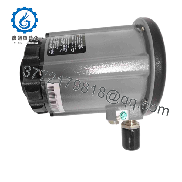
85UVF1A-1QD
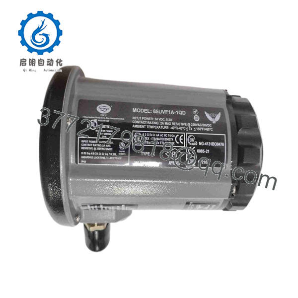
85UVF1A-1QD
Frequently Asked Questions
What is the Fireye 85UVF1A-1QD?
The Fireye 85UVF1A-1QD is a Phoenix Series 2 integrated ultraviolet flame scanner. It uses a solid-state UV sensor and onboard microprocessor to evaluate flame flicker, provide an internal flame relay, and output 4–20 mA DC proportional to flame strength.
What voltage does the 85UVF1A-1QD require?
The scanner requires 24 VDC nominal power and is listed at 200 mA maximum input current. Verify the actual supply voltage at the scanner connector, correct polarity, fuse protection, and voltage drop under operating load before replacing the unit.
What does the “1QD” suffix mean?
The QD designation identifies the 8-pin electrical quick-disconnect connection used by this scanner configuration. The 1A variant includes selectable flame-failure response time. Do not assume that another Phoenix model with a similar base number has the same cable, connector, optics, hazardous-area approvals, or mounting arrangement.
Can this scanner detect infrared flame radiation?
No. The 85UVF model is the ultraviolet version of the Phoenix family and detects UV emissions in the 295–340 nm range. Fireye also makes 85IRF Phoenix scanners for infrared sensing, but they are different models selected for different flame characteristics and applications. Do not substitute UV for IR or IR for UV without a burner-engineering review.
Does it need a separate flame amplifier?
No. The Phoenix 85UVF/IRF family has an internal flame relay with automatically set ON/OFF thresholds, so it does not require a separate remote flame amplifier or flame switch. You still must wire the relay and analog output correctly into the burner-management or safety-control system.
Can I replace an older Fireye Phoenix UV scanner with this model?
Possibly, but confirm the application carefully. Fireye cross-references several older Phoenix UV scanners to the 85UVF1A-1QD. Fireye also warns that when a Phoenix Series 2 scanner replaces an older-generation Phoenix scanner, the mounting flange must be replaced. Confirm the old part number, flange, cable, sight-pipe geometry, relay logic, and FFRT requirements before ordering.
Can I hot-swap the 85UVF1A-1QD while the burner is firing?
No. Do not remove, connect, disconnect, or redirect a flame scanner during burner operation. Place the burner in a safe shutdown condition, isolate fuel and ignition as specified by site procedures, apply lockout/tagout where required, and verify that the combustion system is safe before servicing. A scanner interruption can cause a lockout or create an unsafe flame-proving condition.
What supplier testing should I request?
For New Original / New Surplus stock, request exact part-number verification, label photographs, inspection of the UV lens/window, 8-pin QD connector, mounting flange interface, cable condition, and confirmation that the unit has not been exposed to moisture, corrosion, or impact damage.
For used or refurbished stock, request a documented function test using an approved Fireye-compatible flame-signal test setup or an equivalent controlled test arrangement. The report should confirm 24 VDC power-up, self-diagnostics, relay operation, 4–20 mA signal response, quick-disconnect continuity, FFRT setting verification, and stable operation during a controlled run. Request test photos or video, a written condition statement, warranty terms, and actual-unit photos before shipment.



