
 WhatsApp: +86 16626708626
 Email:
  Phone: +86 16626708626
Description
Key Technical Specifications
| Parameter | Value |
|---|---|
| Product Model | FORCE CPCI-680 |
| Product Family | PowerCore CPCI-680 |
| Form Factor | 6U CompactPCI single-slot SBC |
| CPU | PowerPC G4 7400 |
| CPU Speed | 400 MHz and higher, depending on configuration |
| L2 Cache | 2 MB, operating at half processor speed |
| Onboard SDRAM | Up to 256 MB with ECC |
| Maximum SDRAM | Up to 1 GB with ECC using memory modules |
| User Flash | Up to 16 MB programmable |
| Boot Flash | Two sockets, 512 KB each |
| CompactPCI Interface | Universal PCI-to-PCI bridge |
| CompactPCI Bus | 32-bit, 33 MHz |
| Operating Modes | System slot or peripheral slot |
| Ethernet | Two independent Fast Ethernet interfaces |
| Ethernet Ports | One front-panel 10/100Base-TX; one rear-I/O 10/100Base-TX |
| Serial Interfaces | Two front-panel RS-232; up to four additional rear-I/O RS-232 |
| PMC Expansion | Up to two IEEE P1386.1 PMC slots |
| SCSI | Optional Fast Wide SCSI-2 through PMC |
| CompactFlash | Optional Type II CompactFlash interface |
| RTC / NVRAM | MK48T58, 8 KB NVRAM with real-time clock |
| Watchdog | Integrated watchdog timer |
| Hot Swap | CompactPCI hot-swap support |
| Operating Temperature | 0°C to +55°C with forced-air cooling |
| Storage Temperature | −40°C to +85°C |
| Relative Humidity | 5% to 95%, non-condensing |
| Board Dimensions | 160.00 mm × 233.35 mm |
| Power Example | +5 V at 1.7 A; +3.3 V at 1.9 A for specified 128-400-L1M-16 configuration |
The published datasheet explicitly notes that specifications can change and that complete ordering information depends on the selected configuration. Do not treat the base CPCI-680 designation as sufficient to establish the installed RAM, flash, PMC, SCSI, or processor-speed configuration.
Product Introduction
The FORCE CPCI-680 is a 6U CompactPCI single-board computer built around the PowerPC G4 7400 processor for embedded telecommunications, data communications, industrial control, and government applications. Its SENTINEL universal PCI-to-PCI bridge allows the board to operate as either a CompactPCI system controller or an intelligent peripheral card.
The platform combines dual independent Fast Ethernet, two onboard RS-232 ports, optional SCSI-2, CompactFlash, and up to two PMC expansion slots in one CompactPCI slot. The architecture also supports VxWorks, pSOS, LynxOS, and Linux platforms, making the CPCI-680 suitable for long-lived legacy embedded systems where an exact hardware replacement matters.
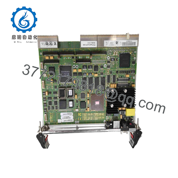
CPCI-680
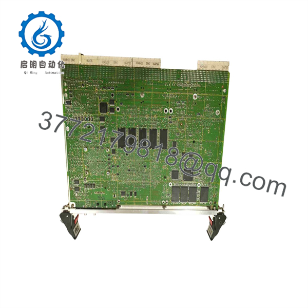
CPCI-680
Installation & Configuration Guide
Stage 1: Pre-Installation Preparation — Approximately 5–10 Minutes
⚠️ Safety First: Put the controlled equipment into its approved safe state before removing a computing module. If the chassis and application do not specifically permit live replacement, remove power and follow the site’s lockout/tagout procedure.
Tools Required:
- ESD wrist strap and grounded ESD work surface
- Appropriate screwdriver for the chassis/module retaining hardware
- Digital multimeter
- Camera or smartphone for connector and configuration records
- Labels for rear-I/O cables
Before removing the existing CPCI-680:
- Record the complete model and configuration suffix from the board label.
- Photograph the front panel, rear-I/O connections, PMC modules, and storage devices.
- Record the installed memory configuration and any CompactFlash media.
- Document the operating system, boot configuration, and application image.
- Record Ethernet configuration, including IP address, subnet, gateway, and MAC-dependent settings where applicable.
- Save application and system configuration files before disturbing the hardware.
⚠️ Do not assume that two boards with the same base model have identical memory or interface configurations. Published variants include different processor speeds, SDRAM capacities, and flash configurations.
Stage 2: Removing the Existing Module — Approximately 5 Minutes
- Confirm that the system is in a safe maintenance state.
- If the CompactPCI chassis does not explicitly support hot replacement for this installation, remove chassis power.
- Disconnect front-panel Ethernet and serial connections as applicable.
- Disconnect or secure rear-I/O cabling associated with the board.
- Remove the board-retaining hardware.
- Release the CompactPCI extraction handles.
- Pull the board straight out of the slot. Do not twist the PCB against the backplane.
- Inspect the backplane connectors for bent contacts, contamination, or mechanical damage.
The datasheet specifies CompactPCI hot-swap support. However, hot replacement is an installation-system function as well as a board feature; confirm that the particular chassis, carrier, operating system, and application support the required hot-swap procedure before removing a live board.
⚠️ Keep the old available until the replacement has completed functional testing.
Stage 3: Installing the Replacement — Approximately 5–10 Minutes
- Attach a grounded ESD strap before handling the replacement board.
- Verify the complete replacement model and configuration against the removed unit.
- Check PMC modules, CompactFlash media, and rear-I/O requirements.
- Verify that the board edge connector and backplane slot are clean.
- Align the with the correct CompactPCI slot guides.
- Insert the board evenly without forcing the connector.
- Secure the front-panel retaining hardware.
- Reconnect Ethernet, serial, rear-I/O, and other required interfaces.
- Reinstall any PMC or storage accessories that belong to the replacement configuration.
Self-Checklist:
- Exact model/configuration verified
- Correct CompactPCI slot confirmed
- PMC configuration verified
- CompactFlash/storage configuration verified
- Rear-I/O connections restored
- Board fully seated
- Retaining hardware secured
- ESD precautions maintained
Stage 4: Power-On & Testing — Approximately 10–15 Minutes
- Before energizing, inspect the board and backplane for foreign objects or visible damage.
- Apply power according to the chassis manufacturer’s startup procedure.
- Observe the status indicators during initialization.
- Verify that the board is recognized in the expected CompactPCI role.
- Confirm whether the board is operating as a system-slot controller or peripheral-slot device.
- Verify the installed operating system and boot sequence.
- Confirm Ethernet link status and network configuration.
- Test the required RS-232 interfaces.
- Verify PMC devices and optional SCSI/CompactFlash functions where installed.
- Start the application software and confirm normal communication with the host system.
- Run the application-specific functional test before returning the equipment to service.
⚠️ If the board powers up but the application does not start, do not immediately assume the CPU board is defective. Check the storage medium, boot configuration, operating-system image, PMC configuration, CompactPCI slot assignment, and application dependencies first.
The provides a watchdog timer, RTC/NVRAM, status indicators, and reset/abort controls, which can assist with startup and fault isolation.
Frequently Asked Questions (FAQ)
Can the FORCE be hot-swapped?
The datasheet specifies full CompactPCI hot-swap support. That does not mean every installed system can safely remove the board under power. The chassis, backplane, operating system, and application must also support the intended hot-swap procedure. If those conditions are unknown, use a controlled power-down replacement.
Is the still a current production product?
The is a legacy Force Computers platform. Current secondary-market documentation identifies units as surplus or used equipment, while the original Force Computers documentation is historical. Treat procurement as a legacy-spares exercise and verify the exact hardware configuration before ordering.
Does every have the same processor and memory configuration?
No. The published platform specification supports PowerPC G4 7400 processors starting at 400 MHz, with up to 256 MB onboard ECC SDRAM and up to 1 GB using memory modules. Actual market units can have different configurations, such as 128 MB/400 MHz or 256 MB/500 MHz versions. Match the replacement to the existing configuration rather than purchasing on the base model number alone.
Can the operate as a peripheral board instead of a system controller?
Yes. Its SENTINEL universal PCI-to-PCI bridge was designed to allow the board to operate in either a CompactPCI system slot or peripheral slot. The manufacturer documentation specifically describes this dual operating capability.
What operating systems can the run?
The published documentation identifies VxWorks, pSOS, LynxOS, and Linux among the supported operating-system platforms. Actual compatibility depends on the installed software image, drivers, PMC devices, and application environment, so an operating-system migration should not be assumed to be plug-and-play.
Does the include Ethernet and serial interfaces?
Yes. The base platform provides two independent Fast Ethernet interfaces and two RS-232 serial interfaces. One Ethernet connection is available on the front panel and the second through rear I/O. Additional serial interfaces can be provided through the optional configuration.
What should I verify before buying a replacement ?
At minimum, compare the complete board identification and configuration, processor speed, SDRAM capacity, user-flash capacity, PMC configuration, storage interface, rear-I/O requirements, and operating-system image. A supplier listing that only states “” does not establish all of these parameters. Ask for photographs of the actual board label and configuration before approving a replacement.



