
 WhatsApp: +86 16626708626
 Email:
  Phone: +86 16626708626
Description
3. Key Technical Specifications
| Parameter | Value |
|---|---|
| Model Family | CPU-5V |
| Manufacturer | Force Computers |
| Product Type | VMEbus Single Board Computer |
| Processor Architecture | SPARC |
| Bus Interface | VMEbus |
| Operating Systems | Solaris, Real-Time OS, Proprietary Embedded OS |
| Form Factor | VME Single Board Computer |
| System Integration | VME Master/Slave Operation |
| Expansion Support | Variant Dependent |
| Memory Configuration | Variant Dependent |
| Network Support | Configuration Dependent |
| Industrial Applications | Factory Automation, Defense, Scientific Systems |
| Product Status | Obsolete Legacy Hardware |
The CPU-5V family was designed around the SPARC architecture and targeted demanding embedded applications including industrial control, military command systems, CAD/CAM, medical imaging, simulation systems, and high-performance data acquisition platforms.
4. Product Introduction
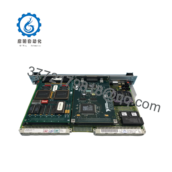
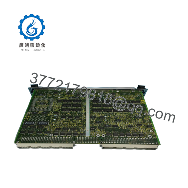
The Force Computers CPU-5V is a SPARC-based VMEbus single-board computer developed for embedded applications requiring UNIX-class processing performance within a VME architecture. Unlike simple controller cards, the CPU-5V functions as the primary processing engine for complex automation, defense, scientific, and telecommunications systems.
In field deployments, CPU-5V systems commonly appear in long-life OEM equipment where software certification and system validation costs make complete platform replacement impractical. Maintaining a working CPU-5V inventory often provides a lower-risk path than migrating to a modern architecture and requalifying the entire application stack.

- CPU-5V
- CPU-5V
5. Installation & Configuration Guide
Stage 1: Pre-Installation Preparation (10 Minutes)
⚠️ Safety First
- Notify operations personnel of planned downtime.
- Place equipment into a safe operating state.
- Apply Lock-Out/Tag-Out procedures.
- Remove all chassis power.
- Wait at least 5 minutes for power supply discharge.
Tools Required
- ESD wrist strap
- PH1 screwdriver
- Fluke 115 multimeter
- Wire labels
- Smartphone camera
- Flashlight
Data Backup
- Backup operating system images.
- Record:
- IP addresses
- Host names
- Boot parameters
- VME slot location
- Photograph:
- Jumper settings
- DIP switches
- SBus or graphics daughtercards
- Front-panel connections
- Document firmware revisions.
Stage 2: Removing the Old Module (5 Minutes)
- Remove retaining screws.
- Label all network and serial cables.
- Disconnect transition-module connections.
- Release ejector handles.
- Pull the board straight outward.
⚠️ Never angle the board during extraction. VME connector damage is one of the most common causes of intermittent bus faults.
- Inspect:
- P1 connector
- P2 connector
- Backplane contacts
- Guide rails
⚠️ Keep the original board available until commissioning is complete.
Stage 3: Installing the New Module (5 Minutes)
Configuration Clone (Critical)
- Connect ESD protection.
- Verify:
- CPU-5V model designation
- Assembly number
- Hardware revision
- Duplicate all switch and jumper settings.
❗ This is the most common rookie mistake, but it happens constantly. Take a picture before you pull it. I can’t stress this enough.
- Insert the board into the VME guides.
- Seat the connectors fully.
- Secure the retaining hardware.
- Reconnect all communications interfaces.
Self-Checklist
- Model numbers match
- Jumpers duplicated
- Firmware documented
- Connectors seated
- Slot location verified
Stage 4: Power-On & Testing (10 Minutes)
Pre-Power Check
- Verify chassis grounding.
- Check power rails for shorts.
- Confirm cooling airflow paths are unobstructed.
Power-Up Procedure
- Energize the VME chassis.
- Observe startup LEDs.
- Connect to the console port.
- Verify boot monitor startup.
- Verify Ethernet connectivity.
- Confirm operating system boot sequence.
- Test VME communication.
Functional Testing
- Verify CPU operation.
- Verify memory detection.
- Verify network communications.
- Verify VME transactions.
- Execute application-level diagnostics.
⚠️ Troubleshooting Note:
- No console output often indicates firmware or NVRAM issues.
- Continuous reboot cycles may indicate corrupted boot parameters.
- VME communication failures frequently result from slot-assignment errors.
Technical Pitfall & Survival Guide
❗ Firmware Revision Mismatch
I’ve seen projects lose an entire weekend because a replacement CPU-5V board carried a different firmware revision than the production system.
The hardware looked identical. The boot process wasn’t.
Avoidance:
- Record firmware versions before removal.
- Request matching firmware revisions.
- Verify boot monitor compatibility.
❗ NVRAM Configuration Loss
Many SPARC-based systems store critical boot information in NVRAM.
A dead battery can prevent normal startup.
Avoidance:
- Backup boot parameters.
- Record environment settings.
- Verify battery condition.
❗ Graphics and Daughtercard Differences
Certain CPU-5V variants include graphics or SBus expansion hardware.
I’ve seen engineers replace the CPU board and forget the attached daughtercard entirely.
Avoidance:
- Photograph the complete assembly.
- Verify installed options.
- Match hardware configurations exactly.
❗ Power Supply Margin Issues
SPARC processor boards typically draw more power than older 68000-based platforms.
A marginal power supply may pass startup tests but fail under load.
Avoidance:
- Measure power rails under load.
- Maintain a 20% power reserve.
- Verify fan operation.
❗ Electrostatic Discharge (ESD)
I once watched an engineer unpack a replacement SPARC board directly from a shipping carton without grounding himself.
The board booted once and never completed POST again.
Avoidance:
- Wear a grounded wrist strap.
- Use an ESD mat.
- Store boards in anti-static packaging.
Keep these checks in mind and you’ll save yourself 90% of typical rework time.
6. Frequently Asked Questions (FAQ)
Q1. What is the FORCE CPU-5V?
The CPU-5V is a SPARC-based VMEbus single-board computer developed by Force Computers for industrial, military, telecommunications, and scientific computing applications.
Q2. Is the CPU-5V obsolete?
Yes.
The platform belongs to a legacy generation of Force Computers VME hardware and has been out of production for many years. Most available inventory comes from surplus stock or refurbished equipment.
Q3. Can I hot-swap the CPU-5V?
No.
Most VME installations using CPU-5V boards were not designed for hot insertion. Power down the chassis before installation or removal.
Q4. What operating systems are commonly used with CPU-5V boards?
Typical deployments include:
- Solaris
- VxWorks
- LynxOS
- Proprietary real-time operating systems
- OEM UNIX-based applications
Actual compatibility depends on the exact board revision and installed firmware.
Q5. Why do identical-looking CPU-5V boards sometimes fail to boot in existing systems?
Firmware and hardware options often differ between revisions.
I’ve seen two boards with nearly identical labels behave completely differently because one contained a different boot monitor revision.
Q6. Why is the CPU-5V still purchased today?
Many industrial and defense systems remain certified around the original hardware platform. Replacing a failed CPU board is often significantly less expensive than rewriting software and recertifying the complete system.
Q7. What should I verify before ordering?
At minimum, verify:
- Exact CPU-5V assembly number
- Hardware revision
- Firmware revision
- Memory configuration
- Installed daughtercards
- Operating system version
- VME chassis compatibility
Without these details, ordering the wrong replacement is surprisingly easy.
Quality Control & Verification Process
1. Inbound Inspection & Traceability
- Verify OEM labels and assembly numbers.
- Confirm serial-number traceability.
- Inspect for:
- Corrosion
- Connector wear
- Rework marks
- UV yellowing
- Audit included accessories.
2. Live Functional Testing
- Install in a known-good VME chassis.
- Verify boot monitor operation.
- Verify console access.
- Test network communication.
- Verify VMEbus transactions.
- Run continuous operation for more than 24 hours.
- Generate an official test report.
3. Electrical Parameter Testing
- 500 V insulation resistance test (>10 MΩ target).
- Ground continuity verification.
- Power rail measurements.
- Connector integrity inspection.
4. Firmware & Configuration Verification
- Record firmware revision.
- Photograph jumper positions.
- Document NVRAM settings.
- Archive configuration records.
5. Final QC & Packaging
- QC inspector sign-off.
- Anti-static ESD bagging.
- Bubble-wrap protection.
- Heavy-duty corrugated carton.
- QC Passed label with inspection date.
For legacy SPARC VME hardware, test photos, console screenshots, burn-in logs, and startup videos should be available upon request. The goal is not to promise failure-free operation; it is to verify that the CPU-5V functions correctly under controlled load testing before shipment.


