
 WhatsApp: +86 16626708626
 Email:
  Phone: +86 16626708626
Description
Key Technical Specifications
| Parameter | Value |
|---|---|
| Manufacturer | Force |
| Model Number | DF02000 |
| Product Type | Industrial Automation Module |
| Primary Function | Control system signal processing/interface |
| Application | Legacy PLC and industrial control installations |
| Installation Type | Control rack/module mounting |
| System Role | Field signal management and automation integration |
| Configuration Method | Original Force system configuration tools |
| Communication Interface | System dependent |
| Power Requirement | System dependent |
| Lifecycle Status | Legacy / EOL risk component |
| Recommended Spare Level | 1-2 units for critical applications |
| Storage Strategy | Controlled inventory with Last-time-buy planning |
Product Introduction & Supply Chain Strategy
The Force DF02000 is an industrial automation module designed for integration within compatible Force control systems. It supports control signal processing and system communication functions in legacy industrial installations where maintaining original hardware architecture is required.
Maintaining DF02000 New Surplus inventory provides a practical lifecycle strategy for plants operating older automation equipment. Securing genuine spare units before supply becomes limited reduces stock-out risk, controls emergency purchasing costs, and improves Total Cost of Ownership (TCO) by avoiding unplanned production interruptions.
Installation & Configuration Guide
Stage 1: Pre-Installation (Prep & Safety)
- Confirm the replacement part number matches the installed Force DF02000 module.
- Review existing control drawings and system documentation.
- Perform lock-out/tag-out procedures before hardware replacement.
- Wear a grounded ESD wrist strap when handling the module.
- Record existing configuration information:
- Firmware or software revision
- Module address settings
- DIP switch positions
- Communication parameters
- Photograph:
- Module wiring
- Terminal connections
- Rack position
- Jumper settings
- Prepare required tools:
- ESD protection equipment
- Screwdrivers
- Multimeter
- Approved electrical test tools
Stage 2: Removal
- Shut down system power according to plant procedures.
- Verify voltage absence before touching the module.
- Disconnect field wiring carefully.
- Label each connection before removal.
- Release mounting hardware.
- Remove the DF02000 module straight from the rack or mounting assembly.
- Avoid excessive force that could damage connectors or backplane pins.
Stage 3: Installation (Clone & Seat)
- Verify the replacement DF02000 matches the original hardware revision.
- Transfer DIP switch and jumper settings exactly.
- Confirm the correct installation location.
- Align the module connector carefully.
- Seat the module evenly into position.
- Reconnect field wiring according to the recorded documentation.
- Verify terminal tightness before power restoration.
Stage 4: Power-On & Testing
- Inspect all wiring before applying power.
- Verify supply voltage levels.
- Check for wiring shorts before startup.
- Restore system power.
- Monitor module status indicators:
- RUN indicates normal operation.
- ERR indicates diagnostic attention is required.
- Verify communication with the controller.
- Test connected I/O signals.
- Confirm normal machine or process operation.
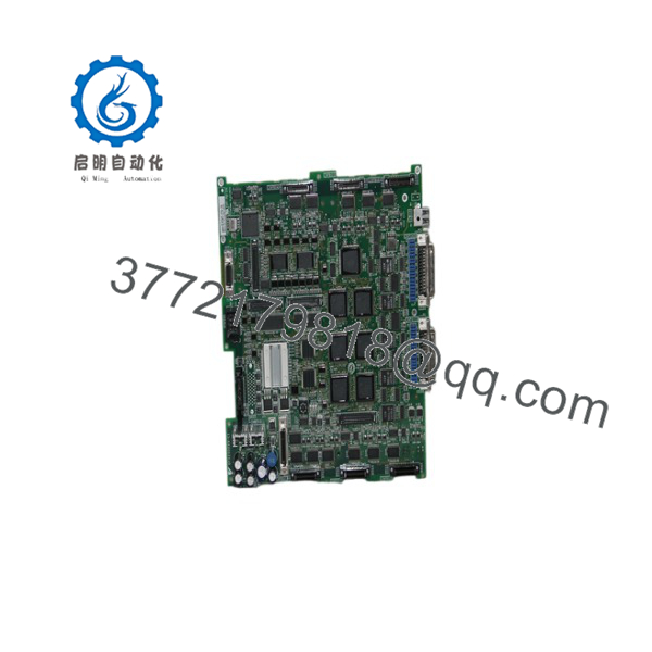
DF02000
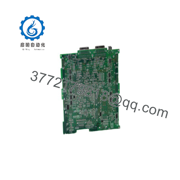
DF02000
Firmware/Software Versions & Upgrade Notes
- Recommended Firmware Version: Match the firmware revision of the existing installation whenever possible.
- Compatibility Requirement: Confirm compatibility between the hardware revision, controller software, communication configuration, and application logic.
- Firmware Upgrade Risk: Firmware changes during replacement may introduce communication errors, configuration mismatches, or unexpected system behavior.
- Firmware Downgrade Risk: Returning to older firmware may affect stored parameters and application compatibility.
Critical Replacement Notes:
- Document original firmware before removal.
- Save PLC/application backups.
- Record module addressing information.
- Verify communication parameters after installation.
- Confirm I/O mapping before returning equipment to production.
Frequently Asked Questions (FAQ)
Q1: Is the Force supplied as a new unit?
Yes. The is supplied as a Brand New Surplus unit. It is original inventory with quality verification and traceability documentation. It is not from a decommissioned installation and is not refurbished.
Q2: Why does New Surplus cost more than repaired alternatives?
New Surplus inventory maintains original manufacturing condition and avoids unknown component aging. Lower-cost repaired parts may introduce additional maintenance risk because internal component history is difficult to verify.
Q3: Is the still actively manufactured?
The is treated as a legacy automation component. Plants using this module should monitor lifecycle status and consider planned Last-time-buy actions.
Q4: How many modules should be stored as spare inventory?
For critical production equipment, maintaining 1-2 units on-site is recommended. For multiple facilities using the same system, vendor consolidation and shared inventory can reduce carrying costs.
Q5: Can the be replaced while powered?
Do not assume hot-swapping capability. Removing automation modules under power may damage electronics or create unexpected control conditions. Follow approved maintenance procedures.
Q6: Will the existing configuration transfer automatically?
Configuration retention depends on the overall control architecture. Always document settings, create backups, and verify addressing before replacing the module.
Q7: What quality documentation is available?
New Surplus units can be supplied with available inspection records, serial verification information, and warranty documentation to support procurement and maintenance traceability.



