
 WhatsApp: +86 16626708626
 Email:
  Phone: +86 16626708626
Description
3. Key Technical Specifications
| Parameter | Value |
|---|---|
| Processor | Motorola MC68030 |
| CPU Clock | 25 MHz |
| Floating Point Coprocessor | Motorola 68882 |
| Architecture | 32-bit |
| Bus Interface | VMEbus |
| Memory Capacity | 4 MB to 32 MB (revision dependent) |
| SRAM | 32 KB standard |
| Flash Memory | Up to 4 MB |
| Ethernet Interface | Integrated Ethernet Controller |
| Serial Ports | Up to 4 serial interfaces |
| SCSI Interface | Supported |
| Real-Time Clock | Battery-backed RTC |
| Operating Systems | VxWorks, OS-9, UNIX (application dependent) |
| Installation | Single-slot VME Board |
| Product Status | Obsolete / Legacy Hardware |
4. Product Introduction
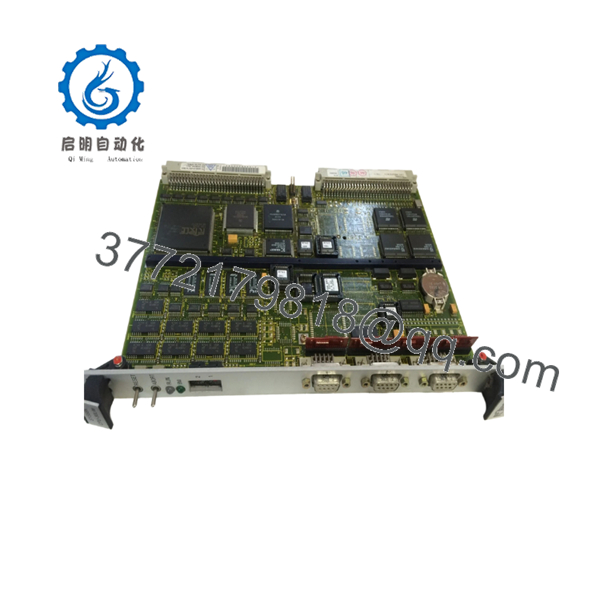
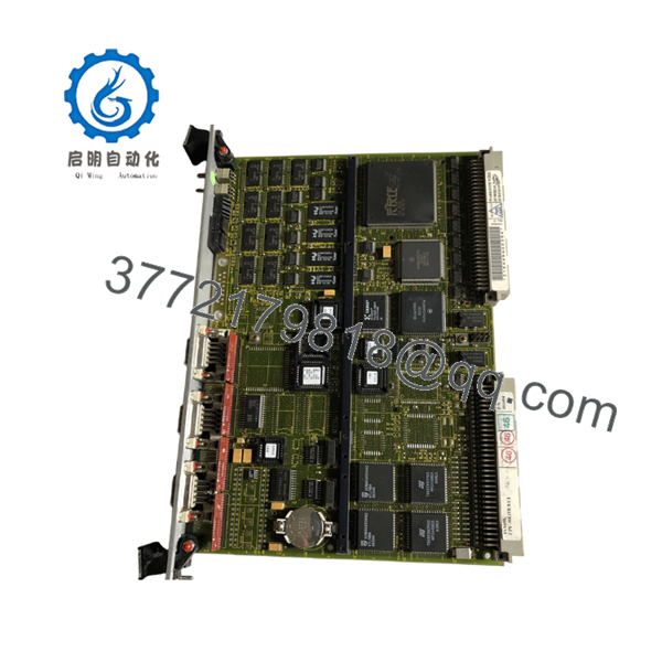
The FORCE SYS68K-CPU-30L is a VMEbus-based industrial CPU module built around the Motorola MC68030 processor. It serves as the central processing unit for legacy automation systems, embedded control platforms, transportation systems, and industrial data acquisition applications.
Engineers continue to maintain CPU-30L installations because many production systems depend on proven VME architectures that remain operational decades after commissioning. The combination of 68030 processing, VMEbus integration, Ethernet capability, serial communications, and optional SCSI support makes the CPU-30L suitable for long-life industrial control systems.

- SYS68K-CPU-30L
- SYS68K-CPU-30L
5. Installation & Configuration Guide
Stage 1: Pre-Installation Preparation (10 Minutes)
⚠️ Safety First
- Notify operations personnel of planned downtime.
- Place the controlled process into a safe state.
- Apply Lockout/Tagout procedures.
- Remove rack power completely.
- Wait at least 5 minutes for power supply discharge.
Tools Required
- ESD wrist strap
- PH1 screwdriver
- Fluke 115 or equivalent multimeter
- Wire labels
- Smartphone for documentation
- Flashlight
Data Backup
- Export application software and configuration files.
- Record network settings and serial port parameters.
- Photograph all front-panel cabling.
- Photograph rotary switches, jumpers, and DIP switches.
- Record firmware revision from maintenance software.
Stage 2: Removing the Old Module (5–10 Minutes)
- Remove the rack cover.
- Label all cables before disconnecting.
- Disconnect communication and I/O connections.
- Loosen front-panel retention screws.
- Pull the board straight from the VME card guides.
- Inspect the backplane connector for bent pins, corrosion, or contamination.
⚠️ Note
Do not discard the original module until startup testing is complete.
Stage 3: Installing the New Module (10 Minutes)
1. ESD Preparation
- Connect your grounded wrist strap.
- Remove the board from anti-static packaging only when ready to install.
2. Configuration Clone (Crucial)
- Compare all switch settings to the original board.
- Verify:
- Boot configuration
- VME addressing
- Serial communication settings
- Interrupt configuration
❗This is the most common rookie mistake, but it happens constantly. Take a picture before you pull it. I can’t stress this enough.
3. Install the Board
- Confirm the exact model number matches SYS68K-CPU-30L.
- Align with card guides.
- Insert evenly until fully seated.
- Tighten retaining screws.
4. Reconnect Wiring
- Reconnect all communication cables.
- Verify connector orientation.
- Confirm strain relief.
Self-Checklist
- DIP switches match original board
- Jumpers verified
- Board fully seated
- Connectors secured
- Retention screws tightened
Stage 4: Power-On & Testing (15 Minutes)
Pre-Power Check
- Verify chassis ground continuity.
- Measure rack power supply output.
- Check for shorts on power rails.
Power-On Steps
- Energize the VME rack.
- Observe board LEDs during boot.
- Connect through console or maintenance port.
- Verify firmware revision.
- Confirm Ethernet and serial communications.
- Restore application software if required.
- Verify field communications.
- Perform operational testing.
⚠️ Troubleshooting Note
- Solid fault LED: Check firmware compatibility.
- Boot failure: Verify memory and firmware revision.
- No network communication: Check Ethernet configuration and VME addressing.
- Intermittent faults: Inspect backplane connector integrity.
Quality Control & Verification Procedure
1. Inbound Inspection & Traceability
- Verify source documentation.
- Check serial number identification.
- Inspect PCB for corrosion, rework marks, and connector damage.
- Verify accessory inventory when supplied.
2. Functional Testing
- Install board in a compatible SYS68K VME test chassis.
- Verify power-up sequence.
- Confirm serial communication operation.
- Test Ethernet communication.
- Execute continuous burn-in testing for more than 24 hours.
- Generate documented test results.
3. Electrical Testing
- 500 V insulation resistance test (>10 MΩ target).
- Ground continuity verification.
- Power rail measurements under load.
4. Firmware Verification
- Record installed firmware revision.
- Document switch and jumper configuration.
- Photograph board identification labels.
5. Final Packaging
- QC sign-off.
- Anti-static ESD packaging.
- Bubble-wrap protection.
- Heavy-duty corrugated carton.
- QC Passed label with inspection date.
Test photographs and functional test videos should be available upon request.
Common Replacement Pitfalls
❗ Firmware Revision Mismatch
I’ve seen VME systems remain offline for days because a replacement board carried a newer firmware revision than the original unit.
Avoidance:
- Record firmware before removal.
- Request matching firmware whenever possible.
- Verify compatibility with operating system and application software.
❗ DIP Switch and Jumper Configuration Errors
A replacement board shipped from inventory often arrives with factory default settings.
Avoidance:
- Photograph everything before removal.
- Duplicate settings exactly.
- Verify address assignments before startup.
❗ Connector and Interface Differences
Several CPU-30 variants appear identical externally but differ internally.
Avoidance:
- Confirm exact part number.
- Verify revision markings.
- Review installation documentation.
❗ Power Budget Problems
Legacy VME systems often operate near power supply limits.
Avoidance:
- Measure power supply loading.
- Maintain at least 20% capacity margin.
- Verify cooling airflow throughout the rack.
❗ Electrostatic Discharge (ESD)
I once watched a technician unpack a replacement CPU during winter conditions without grounding himself. The board never completed boot diagnostics afterward.
Avoidance:
- Use ESD protection at all times.
- Store boards in anti-static packaging.
- Avoid carpeted work areas.
Keep these checks in mind and you’ll save yourself 90% of typical rework time.
6. Frequently Asked Questions (FAQ)
Q1. Can I hot-swap the SYS68K-CPU-30L?
No.
The CPU-30L is installed on a VMEbus backplane and was not designed for hot-swapping. Removing the board under power can corrupt the bus or damage connected hardware.
Q2. Is the SYS68K-CPU-30L obsolete?
Yes.
The CPU-30 series is a legacy platform. Most available inventory comes from surplus stock, system decommissioning projects, or specialized industrial inventory providers.
Q3. Is the board genuinely new?
Inventory condition varies.
Typical market conditions include:
- New Original
- New Surplus
- Refurbished (tested)
- Used (tested)
Request photographs, test reports, and serial number documentation before purchase.
Q4. Will I lose my application software during replacement?
Not necessarily, but never assume software resides entirely on the replacement board.
Before removal:
- Back up the application.
- Record firmware versions.
- Save configuration data.
- Verify storage media integrity.
Q5. What processor does the SYS68K-CPU-30L use?
The CPU-30 family uses the Motorola MC68030 processor operating at 25 MHz and typically includes a Motorola 68882 floating-point coprocessor.
Q6. What operating systems are commonly used with this platform?
Depending on the application, CPU-30 systems have been deployed with VxWorks, OS-9, UNIX variants, and proprietary embedded software environments.
Q7. What should be verified before ordering a replacement?
Verify:
- Exact model number
- Hardware revision
- Firmware revision
- Memory configuration
- Ethernet option
- SCSI option
- Existing operating system requirements
For SYS68K systems, firmware and hardware revision matching is often more important than cosmetic condition.


