
 WhatsApp: +86 16626708626
 Email:
  Phone: +86 16626708626
Description
3. Key Technical Specifications
| Parameter | Specification |
| Processor Type | Motorola MC68030 32-bit microprocessor (with internal MMU) |
| Clock Frequency | 16 MHz, 20 MHz, or 25 MHz variants |
| Floating Point Unit | MC68882 math coprocessor (FPU) |
| On-Board Memory | 1 MB to 4 MB dual-ported SRAM with zero-wait-state read/write |
| EPROM Sockets | 4x 32-pin JEDEC sockets for boot/system flash up to 4 MB |
| VMEbus Interface | Full Master/Slave compliance, Level A32:D32 / D16 / D08 |
| Interrupter/Handler | Slot-1 system controller functionality with 7-level interrupt handler |
| Serial Communication | 2x multiprotocol serial channels (RS-232C / RS-422 interface) |
| Real-Time Clock | Integrated battery-backed RTC with watch function |
| Power Consumption | +5 V DC, ±5% |
| Form Factor | Standard Double-Height (6U) VMEbus board |
4. Product Introduction & Supply Chain Strategy
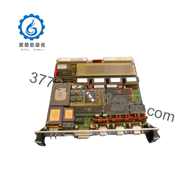
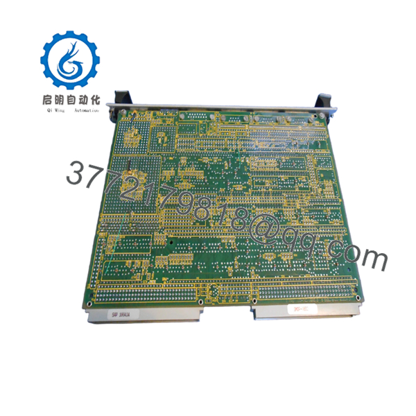
The FORCE SYS68K-CPU-30X is a high-performance 32-bit VMEbus single board computer engineered around the Motorola 68030 architecture. Featuring an integrated Memory Management Unit (MMU) and an MC68882 math coprocessor, this board was designed to handle intensive algorithmic workloads, complex process control, and high-speed data acquisition in aerospace, defense, and heavy industrial automation sectors.
As an absolute End-of-Life (EOL) component, the SYS68K-CPU-30X represents a critical vulnerability in legacy control architectures. A sudden failure of this master processor panel halts the entire VME chassis, resulting in immediate and costly facility downtime. Securing a verified New Surplus board provides an instantaneous drop-in solution that maintains original timing characteristics and firmware execution. Choosing our original new stock over a third-party repaired board eliminates the risk of underlying component fatigue, reduces Total Cost of Ownership (TCO), and provides the necessary capital efficiency to bypass a forced, multimillion-dollar system migration.

- SYS68K-CPU-30X
- SYS68K-CPU-30X
5. Installation & Configuration Guide
Stage 1: Pre-Installation (Prep & Safety)
- De-energize the entire VME chassis and follow standard plant lock-out/tag-out rules to prevent electrical arcing.
- Put on a grounded ESD wrist strap and ensure it is properly bonded to the unpainted metal chassis framework.
- Document all onboard jumper matrices and DIP switch banks on the existing board. Use high-resolution photographs to capture node addresses, VME memory base mapping, and interrupt priority levels.
Stage 2: Removal
- Unthread the upper and lower faceplate locking screws anchoring the module to the subrack card cage.
- Flip the board’s top and bottom ejector handles outward simultaneously to smoothly break the high-density connection with the backplane.
- Slide the board out along the plastic chassis card guides, handling the unit solely by the front metal panel and the rigid edges of the PCB.
Stage 3: Installation (Clone & Seat)
- Place both the old module and the new FORCE SYS68K-CPU-30X side-by-side on a static-dissipative work surface.
- Match the jumper blocks on the new board exactly to the layout mapped on the original unit to ensure identical memory addressing and interrupt mapping.
- Align the board edges with the chassis guide slots and slide the board inward until the rear pins meet the DIN 41612 backplane connectors. Compress the ejector ears inward to fully drive the board into place, then secure the faceplate screws.
Stage 4: Power-On & Testing
- Verify no foreign objects or stray wiring remnants remain in the slot, then power up the VME chassis supply.
- Check the front-panel indicator array during initialization. The red HALT and amber RUN lights should cycle during the power-on self-test (POST).
- Confirm that the RUN LED stays continuously lit and the local error indicator remains dark. Connect a terminal window to Serial Port A to monitor boot routines and ensure communication handshakes with adjacent I/O modules are successfully established.
6. Firmware/Software Versions & Upgrade Notes
The operational logic of the FORCE SYS68K-CPU-30X is tied directly to the system software stored inside its physical, socketed JEDEC EPROMs. Real-time operating systems common to this hardware generation, such as VxWorks, OS-9, or custom machine code binaries, rely on precise memory addresses matching the onboard firmware revision.
⚠️ CRITICAL INTEGRATION ALERT: Moving from an older CPU hardware revision to the “X” variant may shift specific internal register positions. If your system application relies on low-level firmware version matches, do not swap this hardware without first transferring your original application EPROMs directly into the sockets of the new board. Failing to match firmware configurations can trigger immediate bus error traps (BERR), local memory allocation faults, or an absolute failure to communicate with surrounding VME memory and peripheral cards.
7. Frequently Asked Questions (FAQ)
Q: What distinguishes a “New Surplus” board from a refurbished or repaired card?
A: Our New Surplus units have never been put into active service, deployed on a plant floor, or harvested from a decommissioned assembly. They represent original, pristine factory stock stored in climate-controlled environments. Unlike refurbished options—which often hide thermal degradation, component aging, or trace repairs beneath fresh conformal coating—these modules deliver baseline OEM reliability with zero wear on backplane connection pins.
Q: Why should my company pay a premium for a New Surplus board when used alternatives exist?
A: Buying used or repaired boards creates a critical single point of failure within your legacy systems. A cheap, unverified part might save procurement capital upfront, but an early failure can easily cost tens of thousands of dollars in emergency engineering overhead and unplanned production outages. This New Surplus hardware represents an operational insurance policy, delivering a predictable 10-to-15-year lifecycle and a lower Total Cost of Ownership (TCO).
Q: Does this board support hot-swapping if an unexpected module failure occurs?
A: Absolutely not. The standard VMEbus architecture used by the SYS68K series does not incorporate the specialized pin staging or power isolation circuitry required for live insertion. Attempting to install or pull this processor while the backplane is energized will trigger severe voltage spikes across the data lines. This can instantly ruin the MC68030 processor, scramble on-board RAM structures, and permanently damage other cards sharing the VME backplane lines.
Q: How does the “30X” version differ fundamentally from standard “30” models?
A: The “X” designation typically indicates extended memory support, optimized trace layouts for higher clock rates (such as 25 MHz operations), or specific architectural updates to the onboard VMEbus master interface interface logic. It is critical to verify your existing jumper assignments, as base memory mapping points can vary between standard and extended “X” revisions.
Q: What steps are taken to verify the quality of the board before it leaves your facility?
A: Every board goes through an extensive quality assurance process. This includes inbound physical verification, anti-counterfeit inspection of component serial markers, and live functional testing inside a standardized VMEbus test rack to verify valid power-on initialization, terminal communication via the serial ports, and error-free backplane bus handshakes.
Q: What is the warranty coverage provided with this FORCE processor module?
A: This module is backed by a full 1-year warranty covering material integrity and operational functionality. This long-term warranty reflects the pristine condition of our unused inventory and provides your engineering and procurement teams with complete peace of mind, far exceeding the minimal 30-day guarantees common with secondary market suppliers.


