
 WhatsApp: +86 16626708626
 Email:
  Phone: +86 16626708626
Description
3. Key Technical Specifications
| Parameter | Value |
|---|---|
| Processor | Motorola MC68060 |
| CPU Clock Frequency | 50 MHz |
| CPU Bus Frequency | 25 MHz |
| Architecture | 32-bit |
| VMEbus Interface | A32/D32 Master/Slave with DMA |
| DRAM Options | 4 MB, 8 MB, 16 MB, 32 MB onboard |
| Maximum Memory | Up to 128 MB with expansion modules |
| SRAM | Battery-backed SRAM available |
| Ethernet | Integrated Ethernet Interface |
| Serial Ports | 2 × RS-232 Front Panel Ports |
| Storage Interface | SCSI-2 Supported |
| Real-Time Clock | Battery-backed RTC |
| Boot PROM | Up to 1 MB configuration dependent |
| Operating Systems | VxWorks, OS-9, UNIX variants |
| Power Consumption | +5 V @ 3.5 A typical (32 MB version) |
| Installation Type | Single-Slot VME Board |
| Product Status | Obsolete / Legacy Hardware |
4. Product Introduction
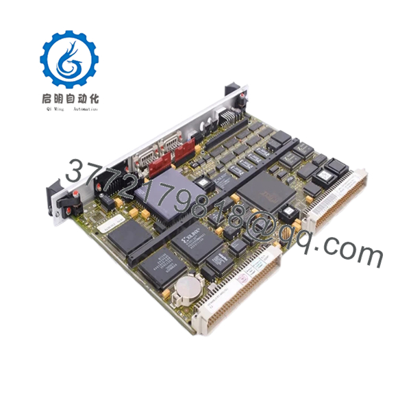
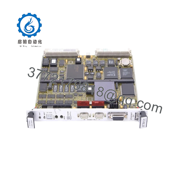
The FORCE SYS68K-CPU-60D is a high-performance VMEbus single-board computer built around the Motorola MC68060 processor. It serves as the central controller in industrial automation systems, transportation platforms, telecommunications infrastructure, defense applications, and embedded real-time control systems.
Compared with earlier 68030-based SYS68K boards, the CPU-60D delivers substantially higher processing capacity while maintaining compatibility with existing VMEbus infrastructures. Integrated Ethernet, SCSI-2 support, DMA capability, and battery-backed memory made it a common choice for mission-critical control systems throughout the 1990s and early 2000s.

- SYS68K-CPU-60D
- SYS68K-CPU-60D
5. Installation & Configuration Guide
Stage 1: Pre-Installation Preparation (10 Minutes)
⚠️ Safety First
- Notify operations personnel of planned downtime.
- Place the process into a safe operating condition.
- Apply Lockout/Tagout procedures.
- Remove all rack power.
- Wait at least 5 minutes for capacitor discharge.
Tools Required
- ESD wrist strap
- PH1 screwdriver
- Fluke 115 or equivalent multimeter
- Wire labels
- Smartphone for documentation
- Flashlight
Data Backup
- Back up operating system and application software.
- Record IP addresses and serial communication settings.
- Photograph all front-panel connections.
- Record all DIP switch and jumper settings.
- Document firmware revision and boot monitor version.
Stage 2: Removing the Old Module (5–10 Minutes)
- Remove cabinet access panels.
- Label all communication cables.
- Disconnect Ethernet, serial, and peripheral connections.
- Remove front-panel retaining screws.
- Extract the board straight from the VME card guides.
- Inspect P1 and P2 backplane connectors for contamination or damage.
⚠️ Note
Retain the original board until startup and acceptance testing are complete.
Stage 3: Installing the New Module (10 Minutes)
1. ESD Preparation
- Wear a grounded wrist strap.
- Remove the replacement board from anti-static packaging only when ready to install.
2. Configuration Clone (Crucial)
Verify:
- Boot source settings
- VMEbus arbitration settings
- System controller configuration
- Memory options
- Serial communication parameters
❗ This is the most common rookie mistake, but it happens constantly. Take a picture before you pull it. I can’t stress this enough.
3. Install the Board
- Confirm the exact model number is SYS68K-CPU-60D.
- Verify memory configuration matches system requirements.
- Align board guides carefully.
- Insert fully into the backplane.
- Tighten retention hardware.
4. Reconnect Wiring
- Reconnect Ethernet and serial interfaces.
- Verify connector orientation.
- Inspect cable strain relief.
Self-Checklist
- DIP switches match original
- Jumpers verified
- Board fully seated
- Cables secured
- Retention screws tightened
Stage 4: Power-On & Testing (15 Minutes)
Pre-Power Check
- Verify chassis grounding.
- Measure power supply voltage.
- Check power rails for shorts.
Power-On Steps
- Energize the VME chassis.
- Observe LED startup sequence.
- Connect through Serial Port 1 console.
- Verify VMEPROM startup messages.
- Confirm firmware revision.
- Verify Ethernet communication.
- Test serial interfaces.
- Restore application software if required.
- Verify field communications.
⚠️ Troubleshooting Note
- Red fault indication: Check firmware compatibility and memory configuration.
- No console output: Verify serial port settings and boot configuration.
- VMEbus faults: Inspect arbitration and system controller settings.
- Communication failures: Verify Ethernet configuration and network parameters.
Quality Control & Verification Procedure
1. Inbound Inspection & Traceability
- OEM label verification
- Serial number documentation
- Connector inspection
- PCB inspection for corrosion, repairs, or damaged traces
- Accessory verification
2. Live Functional Testing
- Installed in a compatible SYS68K VME test rack
- Power-on diagnostics verification
- Ethernet communication testing
- RS-232 communication testing
- VMEbus DMA operation verification
- Continuous burn-in testing exceeding 24 hours
3. Electrical Parameter Testing
- 500 V insulation resistance testing
- Ground continuity verification
- Power consumption measurements
- Voltage rail verification under load
4. Firmware Verification
- Firmware revision documentation
- Boot PROM verification
- Switch configuration recording
- Photographic documentation
5. Final QC & Packaging
- QC sign-off
- Anti-static ESD packaging
- Bubble-wrap protection
- Heavy-duty corrugated carton
- QC Passed label with inspection date
Test reports, startup photos, and communication verification videos should be available upon request.
Common Replacement Pitfalls
❗ Firmware Revision Mismatch
I’ve seen CPU-60 systems stay offline for an entire shutdown window because a replacement board carried a newer VMEPROM revision.
Avoidance:
- Record firmware before removal.
- Request matching firmware versions.
- Verify operating system compatibility.
❗ DIP Switch and Jumper Errors
The CPU-60 family has multiple hardware configuration options.
Avoidance:
- Photograph every switch.
- Duplicate settings exactly.
- Verify VMEbus controller settings before startup.
❗ Memory Configuration Differences
CPU-60D boards shipped with multiple memory options.
Avoidance:
- Verify installed DRAM capacity.
- Confirm expansion memory modules.
- Check application memory requirements.
❗ Power Supply Loading
A CPU-60D/32 typically draws approximately 3.5 A from the +5 V rail. Large VME systems can approach supply limits quickly.
Avoidance:
- Calculate total rack load.
- Maintain at least 20% power reserve.
- Verify airflow through the chassis.
❗ Electrostatic Discharge (ESD)
I once watched an engineer install a replacement VME CPU after walking across a carpeted control room. The board never completed POST diagnostics afterward.
Avoidance:
- Use grounded ESD protection.
- Store boards in anti-static packaging.
- Handle boards only by the edges.
Keep these checks in mind and you’ll save yourself 90% of typical rework time.
6. Frequently Asked Questions (FAQ)
Q1. Can I hot-swap the SYS68K-CPU-60D?
No.
The CPU-60D was not designed for hot insertion. Removing or inserting the board while energized can disrupt the VMEbus and damage hardware.
Q2. Is the SYS68K-CPU-60D obsolete?
Yes.
The CPU-60 family is legacy hardware. Most available inventory comes from surplus stock, decommissioned systems, and specialty industrial suppliers.
Q3. What processor does the SYS68K-CPU-60D use?
The board uses a Motorola MC68060 processor operating at 50 MHz with integrated floating-point capability.
Q4. What memory configurations were available?
Standard versions were available with 4 MB, 8 MB, 16 MB, and 32 MB onboard DRAM. Expansion modules could increase total memory to 128 MB.
Q5. Will I lose my application software during replacement?
Not necessarily.
Many installations store applications on external storage, Flash memory, or network-based systems. Always perform a full backup before removing the original board.
Q6. Why do some SYS68K-CPU-60D boards have different suffixes?
Suffixes often identify memory size, option modules, firmware variants, or customer-specific configurations. A SYS68K-CPU-60D/4 and SYS68K-CPU-60D/32 may use identical processors but different memory configurations.
Q7. What should be verified before ordering?
Verify:
- Complete model number
- Memory configuration
- Firmware revision
- VMEPROM version
- Installed option modules
- Operating system requirements
- Ethernet and SCSI requirements
For CPU-60 systems, matching firmware and hardware revisions usually prevents more downtime than any other procurement decision.


