
 WhatsApp: +86 16626708626
 Email:
  Phone: +86 16626708626
Description
3. Key Technical Specifications
| Parameter | Value |
|---|---|
| Processor Architecture | Motorola 68000 Family |
| Product Category | Industrial CPU Board |
| Bus Type | VMEbus |
| Application | Industrial Automation & Embedded Control |
| Operating System Support | Real-Time Operating Systems (version dependent) |
| Memory Type | SRAM/DRAM (configuration dependent) |
| Communication Interfaces | Serial Communication Ports (revision dependent) |
| Installation Type | VME Rack Mount |
| Cooling Method | Passive / Forced Air Cabinet Cooling |
| Operating Temperature | Verify by hardware revision |
| Firmware | Version dependent |
| Product Status | Obsolete / Legacy Hardware |
4. Product Introduction
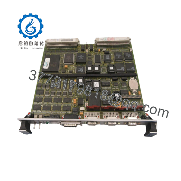
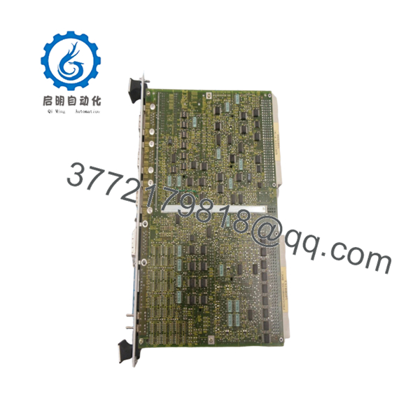
The FORCE SYS68K is a Motorola 68000-based industrial CPU board designed for VMEbus control systems, embedded automation platforms, and legacy industrial computing applications. It was commonly deployed in manufacturing, transportation, test equipment, and process control environments requiring deterministic processing.
Many facilities continue to operate SYS68K platforms because replacing the entire control architecture often costs substantially more than maintaining existing hardware. When sourcing replacement boards, firmware compatibility and exact hardware revision matching are typically more important than the board’s manufacturing date.

- SYS68K
- SYS68K
5. Installation & Configuration Guide
Stage 1: Pre-Installation Preparation (10 Minutes)
⚠️ Safety First
- Notify operations personnel of scheduled downtime.
- Bring the controlled process to a safe operating state.
- Apply Lockout/Tagout (LOTO) procedures.
- Remove system power.
- Wait at least 5 minutes for power supply capacitors to discharge.
Tools Required
- ESD wrist strap
- PH1 screwdriver
- Digital multimeter
- Wire labels
- Smartphone or camera
- Flashlight for rack inspection
Data Backup
- Export application software and configuration files.
- Record network and communication settings.
- Photograph all cabling connections.
- Document board slot location.
- Photograph jumpers and DIP switch settings.
Stage 2: Removing the Old Module (5–10 Minutes)
- Remove the cabinet cover or rack access panel.
- Label all external connections.
- Disconnect cables carefully.
- Loosen board retention screws.
- Pull the SYS68K straight out of the VME chassis using even pressure.
- Inspect the backplane connectors for damage, contamination, or bent pins.
⚠️ Note
Keep the removed module available until commissioning is complete. It remains your best reference source if configuration questions arise.
Stage 3: Installing the New Module (10 Minutes)
1. ESD Preparation
- Wear a grounded wrist strap.
- Handle the board by the edges only.
- Avoid touching IC pins or connector contacts.
2. Configuration Clone (Crucial)
- Match every jumper and DIP switch position.
- Verify:
- Node address settings
- Boot mode selections
- Communication settings
- Bus termination options
❗This is the most common rookie mistake, but it happens constantly. Take a picture before you pull it. I can’t stress this enough.
3. Install the Board
- Verify exact model and assembly number.
- Align the board with card guides.
- Insert evenly into the backplane.
- Tighten retaining hardware.
4. Reconnect Wiring
- Reattach all communication cables.
- Verify connector orientation.
- Confirm cable strain relief.
Self-Checklist
- DIP switches match original board
- Jumpers verified
- Board fully seated
- Wiring secured
- Retention hardware tightened
Stage 4: Power-On & Testing (10–15 Minutes)
Pre-Power Check
- Measure 24 V supply output.
- Check for shorts between power and ground.
- Verify chassis grounding continuity.
Power-On Steps
- Power the rack only.
- Observe boot LEDs.
- Monitor startup sequence.
- Connect maintenance software or terminal session.
- Verify firmware revision.
- Confirm communication with connected devices.
- Perform I/O verification testing.
- Return field devices to service.
⚠️ Troubleshooting Note
- Solid fault LED: Check firmware compatibility first.
- No communication: Verify node address, baud rate, and termination settings.
- Intermittent operation: Inspect backplane connectors and power supply ripple.
Common Replacement Pitfalls
❗ Firmware Revision Mismatch
I’ve seen projects where a technician installed a newer CPU board and spent two days chasing communication alarms. The issue wasn’t wiring—it was a firmware revision change that altered protocol behavior.
Avoidance:
- Document existing firmware before removal.
- Request specific firmware revisions when ordering.
- Verify compatibility with connected controllers and HMIs.
❗ DIP Switch and Jumper Errors
This causes more startup failures than defective hardware.
Avoidance:
- Photograph every switch position.
- Duplicate settings exactly.
- Verify node addresses before power-up.
❗ Terminal and Connector Differences
Even visually similar board revisions may use different connector assignments.
Avoidance:
- Review original documentation.
- Compare part numbers carefully.
- Verify pinouts before reconnecting field wiring.
❗ Power Supply Capacity
Older installations often run close to their power budget.
Avoidance:
- Calculate total rack consumption.
- Maintain at least a 20% capacity margin.
- Verify supply voltage under load.
❗ Electrostatic Discharge (ESD)
I once watched an engineer unpack a replacement board during winter conditions without grounding himself. The board failed immediately at startup.
Avoidance:
- Use an ESD wrist strap.
- Store boards in anti-static packaging.
- Work only on grounded surfaces.
Keep these checks in mind and you’ll save yourself 90% of typical rework time.
6. Frequently Asked Questions (FAQ)
Q1. Can I hot-swap the FORCE SYS68K under power?
No.
Most SYS68K implementations were not designed for hot-swapping. Removing or inserting a board while energized can corrupt the VME bus, crash the controller, or damage backplane components. Shut down the rack before replacement.
Q2. Is the FORCE SYS68K obsolete?
Yes.
The SYS68K platform is considered legacy hardware and is no longer in mainstream production. Availability typically comes from surplus inventory, decommissioned systems, or specialized industrial stock providers.
Q3. Is the unit genuinely new or refurbished?
This depends on inventory source.
- New Original / New Surplus: Unused legacy stock from original inventory.
- Refurbished: Previously deployed hardware that has been cleaned, tested, and verified operational.
Always request photos and test documentation before purchase.
Q4. Will I lose my application program when replacing the CPU board?
Possibly.
Some SYS68K installations store application data on external media, while others rely on onboard memory or storage modules.
Before removal:
- Back up the application.
- Record firmware versions.
- Verify storage media integrity.
Never assume the replacement board contains your application software.
Q5. What is the direct replacement if SYS68K stock is unavailable?
There is no universal drop-in replacement.
The correct migration path depends on:
- Hardware revision
- Operating system
- VME architecture
- Connected I/O hardware
A migration assessment is normally required before selecting a replacement platform.
Q6. Why is surplus inventory often cheaper than OEM pricing?
Because the hardware is typically sourced from:
- Project overruns
- Unused maintenance inventory
- Plant decommissioning stock
- Distributor excess inventory
Lower pricing does not automatically indicate lower quality. What matters is documented testing and traceability.
Q7. What testing should be performed before shipment?
A qualified supplier should provide:
- Serial number verification
- Visual inspection records
- Power-on verification
- Communication testing
- 24-hour burn-in testing
- Insulation resistance testing
- Firmware documentation
- QC inspection records
Test photos and videos should be available upon request. Verify precise compatibility with OEM documentation before installation.


