
 WhatsApp: +86 16626708626
 Email:
  Phone: +86 16626708626
Description
Key Technical Specifications
| Parameter | Value |
|---|---|
| Manufacturer | Foxboro, a Schneider Electric process automation brand |
| Model Number | 871EC-SP0 |
| Product Family | 871EC Electrodeless Conductivity Sensors |
| Sensor Technology | Electrodeless / toroidal / inductive conductivity measurement |
| Sensor Body Code | -SP small-bore configuration |
| Sensor Body Material | Glass-filled PEEK |
| Temperature Compensator | Integral 100 kΩ thermistor |
| Process Temperature Range | −5 to +120 °C; 20 to 250 °F |
| Process Pressure Range | −0.1 to +1.75 MPa; −15 to +250 psi |
| Conductivity Range | 1.0 to 2,000 mS/cm; 1,000 to 2,000,000 µS/cm |
| Minimum In-Line Pipe Size | DN 80; 3 in minimum to reduce pipe-wall effects |
| Mounting Options | Insertion, flange, bushing, retractable, or in-situ installation depending on the accessory assembly |
| Compatible Analyzers/Transmitters | Foxboro 875EC, 873EC, 873AEC, 870ITEC, and 870EC families; verify exact instrument configuration |
| Typical Applications | Brine, salinity, steel pickling, scrubbers, ion-exchange regeneration, plating baths, rinse water, caustic cleaning, and textile process liquids |
| Lifecycle Status | Legacy process analytical sensor; stock and cable-length suffix availability vary by supplier |
The 871EC-SP sensor is the small-bore standard-temperature PEEK version of Foxboro’s electrodeless conductivity sensor family. Published Foxboro documentation specifies its 100 kΩ thermistor, −5 to +120 °C temperature range, −0.1 to +1.75 MPa pressure range, 1.0 to 2,000 mS/cm conductivity range, and 3 in minimum in-line pipe requirement.
Product Introduction
The Foxboro 871EC-SP0 is an electrodeless, toroidal conductivity sensor for measuring conductivity in conductive process liquids. Its glass-filled PEEK body and integral 100 kΩ thermistor support conductivity measurement with temperature compensation in applications such as chemical cleaning, brine handling, scrubbers, plating, ion-exchange regeneration, and rinse-water systems.
Unlike contacting conductivity cells, the 871EC-SP design places no exposed measurement electrodes in the liquid. That helps reduce electrode fouling and polarization issues in dirty or chemically aggressive services. The sensor must still be correctly centered in a sufficiently large pipe and paired with a compatible Foxboro analyzer or transmitter.
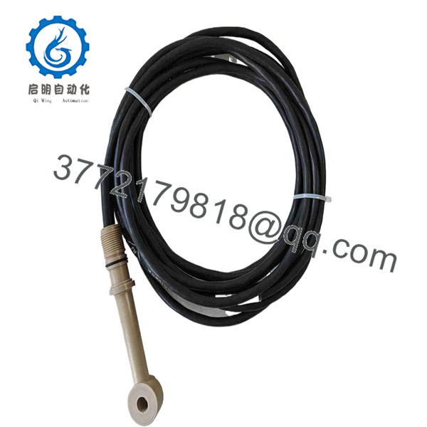
871EC-SP0
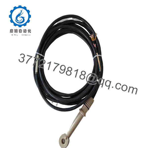
871EC-SP0
Troubleshooting Quick Reference
| Symptom | Possible Cause | Relevance to this Part | Quick Check Method | Recommendation |
|---|---|---|---|---|
| Conductivity reads zero or very low | Open sensor cable, disconnected plug, failed analyzer input, nonconductive process fluid, sensor coil failure | ✅ Medium | Verify the analyzer status and inspect the entire sensor cable for cuts, crushed sections, moisture ingress, and loose terminations. Compare the process liquid with an independent sample measurement where possible. | Check the analyzer and cable before replacing the sensor. Replace the sensor if the cable and analyzer are verified healthy and the sensor fails a manufacturer-approved test. |
| Conductivity reads excessively high | Incorrect range or calibration, conductive coating or liquid bridge, process contamination, wrong sensor configuration | ✅ Medium | Inspect the sensor mounting area for buildup and trapped conductive liquid. Confirm the configured sensor type, cell factor, temperature compensation, and conductivity range in the analyzer. | Clean the sensor using a process-compatible method, then verify configuration and calibrate against a known standard if the procedure permits. |
| Reading is noisy or unstable | Air bubbles, poor grounding, electrical interference, unstable flow, damaged cable, improper sensor immersion | ✅ Medium | Trend the value while checking pump operation, flow stability, nearby VFD/RF interference, and sensor position. Inspect grounding and cable shielding according to the installation drawing. | Correct the installation, flow, grounding, and cable issue first. Replace the sensor only if instability follows the sensor after controlled checks. |
| Reading changes when a pump starts or stops | Air entrainment, changing concentration, turbulence, electrical noise, poor pipe location | ❌ Low to medium | Observe process flow and check whether bubbles collect around the sensor. Confirm the sensor is installed in a full pipe and away from locations that trap air. | Relocate or reorient the sensor if installation conditions violate the manual. Do not replace a sensor for a process-flow problem. |
| Temperature reading is wrong | Open or shorted 100 kΩ thermistor, cable damage, incorrect analyzer temperature-compensation setting | ✅ High | Compare displayed temperature with a calibrated reference thermometer near the sensor. With the loop isolated, measure thermistor resistance and compare it with the applicable temperature-resistance table. | Verify cable continuity and analyzer configuration. Replace the sensor if the integral thermistor is defective. |
| Reading is inaccurate after sensor replacement | Wrong sensor type selected, incorrect temperature compensation, unsuitable installation geometry, retained old calibration | ✅ High | Confirm the analyzer is configured for 871EC-SP, the correct temperature element, and the intended engineering range. Verify the sensor is centered in a minimum 3 in process line. | Correct configuration and installation before recalibration. Document the old settings before removing the original sensor. |
| Process leak appears around the insertion point | Damaged O-ring, wrong seal material, scratched seating surface, improper torque, incorrect mounting hardware | ✅ High | Isolate and depressurize the line. Inspect O-rings, gasket surfaces, insertion hardware, and valve assembly for damage or chemical attack. | Replace seals with process-compatible parts and reinstall using the approved torque procedure. Perform a pressure and leak test before returning to service. |
| Sensor body is cracked, swollen, or chemically attacked | Incompatible chemical, excessive temperature, overpressure, mechanical impact, incorrect cleaning method | ✅ High | Remove the sensor safely and inspect the PEEK body, cable entry, and sealing surfaces. Compare the actual process conditions with the stated limits. | Replace the sensor. Review chemical compatibility, maximum temperature, maximum pressure, and cleaning procedures before installing the new unit. |
❗ Do not install it in an undersized pipe: The published guidance calls for a minimum DN 80, or 3 in, in-line pipe size for the -SP sensor to avoid pipe-wall effects. A sensor installed too close to a pipe wall can deliver a stable but inaccurate reading.
❗ Confirm the sensor code before ordering: “871EC-SP0” is a family/configuration designation. Cable-length suffixes such as 871EC-SP0-3 or 871EC-SP0-4 appear in reseller listings. Verify the exact full label, cable length, termination type, mounting hardware, and analyzer interface before buying.
❗ Air bubbles cause false conductivity values: A toroidal sensor needs consistent liquid coupling around its sensing area. A partially filled line, vortex, or bubble pocket can cause drifting or erratic values that are not a sensor failure.
❗ Do not substitute seal materials casually: The PEEK sensor body may tolerate the process, while a mismatched O-ring may not. Confirm compatibility with the chemical, temperature, pressure, and cleaning chemistry before installation.
❗ Protect the cable: The sensing element can be fine while the cable is damaged by cable trays, cabinet doors, vibration, or chemical exposure. Check cable routing and strain relief before calling the sensor defective.
Keep these checks in mind and you will save yourself 90% of typical rework time. If the fault remains unclear, contact technical support with sensor-label photographs, analyzer model and configuration, conductivity and temperature trends, process conditions, cable length, and installation photographs.
Frequently Asked Questions
What does the Foxboro 871EC-SP0 measure?
The 871EC-SP0 measures the electrical conductivity of conductive liquids using electrodeless, toroidal sensing technology. It includes an integral 100 kΩ thermistor so a compatible Foxboro analyzer or transmitter can apply temperature compensation. Typical applications include brine and salinity measurement, scrubbers, ion-exchange regeneration, plating baths, rinse water, and caustic cleaning solutions.
Is the 871EC-SP0 a contacting conductivity cell?
No. It is an electrodeless, also called toroidal or inductive, conductivity sensor. The sensor does not rely on exposed metal electrodes contacting the process liquid in the same way as a conventional contacting cell. That design helps in services where electrode fouling or polarization would create frequent maintenance or unstable readings.
What analyzers work with this sensor?
Published Foxboro documentation lists 875EC communicators, 873EC and 873AEC analyzers, and 870ITEC and 870EC transmitters as compatible product families. Compatibility still depends on the analyzer input hardware, configured sensor type, cable/termination arrangement, and installed system revision. Confirm the analyzer model and configuration before ordering.
Can I install this sensor in a 2 in pipe?
Not for a standard in-line installation if you want to avoid pipe-wall measurement error. Foxboro documentation specifies a minimum DN 80, or 3 in, line size for the -SP sensor when mounted in-line. The compact -SP body can be installed through different hardware arrangements, including insertion, flange, bushing, retractable, and in-situ setups, but the final installation must follow the applicable dimensional drawing and accessory instructions.
Can I hot-swap the sensor from a live pressurized process line?
Only if the installed assembly uses an approved retractable housing and isolation arrangement, and your site procedure explicitly permits it. Do not remove a standard insertion sensor from a pressurized or hazardous process line. Isolate, depressurize, drain, decontaminate, and use the plant’s lockout/tagout and chemical safety procedure before service.
Why does the new sensor read differently from the old one?
First check the analyzer configuration. Confirm that it is set for the correct 871EC-SP sensor type, 100 kΩ temperature element, conductivity range, temperature-compensation method, and engineering units. Then inspect sensor location, pipe size, flow conditions, air bubbles, grounding, cable integrity, and process concentration. A new sensor in the wrong installation position can give a repeatable but misleading result.
Is the 871EC-SP0 obsolete, and is stock limited?
The 871EC family remains documented by Schneider Electric, but exact Foxboro-branded configurations, cable lengths, mounting options, and local inventory may vary. Some reseller records list specific 871EC-SP0 cable variants as out of stock, so confirm the complete suffix, condition, lead time, and availability before placing a purchase order.
Why is a New Surplus conductivity sensor cheaper than factory supply?
New Surplus stock can originate from unused maintenance spares, canceled projects, warehouse liquidations, or inventory held after a site upgrade. The lower price is acceptable only if the supplier clearly states condition and provides clear label photos, cable length, sensor body material, thermistor type, seal condition, packaging condition, warranty terms, and traceability where available.
What inspection and testing should I request before buying?
Request photographs of the full sensor label, PEEK body, cable jacket, cable entry, termination, and any mounting hardware. Confirm that the sensor has no cracks, swelling, deep scratches, chemical residue, or cable damage. For a tested unit, request a documented continuity check of the sensor circuits and 100 kΩ thermistor, plus a conductivity response check using an appropriate standard or approved test solution. Test photos, resistance values, and calibration data should be available upon request.



