
 WhatsApp: +86 16626708626
 Email:
  Phone: +86 16626708626
Description
Key Technical Specifications
| Parameter | Specification |
| Manufacturer | FOXBORO / Invensys / Schneider Electric |
| Model / Part Number | FBM02 / P0400YC |
| Input Channels | 8 galvanically isolated thermocouple/mV input channels |
| Reference Junction | 1 isolated RTD reference junction compensation channel |
| Millivolt Input Range | −10.5 to +71.41875 mV DC (0 to 65,535 raw counts) |
| Accuracy (mV Input) | ±0.035% of span (±0.028 mV) |
| Channel Isolation | 600 V AC withstand for 1 minute (channel-to-channel & channel-to-earth) |
| Input Impedance | 10 MΩ differential |
| Burnout Detection | Configurable upscale indication on sensor open-circuit |
| Operating Voltage | 26 to 42 V DC (redundant power input) |
| Power Consumption | 9 W maximum |
| Operating Temperature | 0 to 60°C (32 to 140°F) |
Product Introduction & Supply Chain Strategy
The FOXBORO FBM02 (P0400YC) is an 8-channel isolated thermocouple and millivolt input module designed for legacy Foxboro I/A Series Distributed Control Systems (DCS). It processes low-level analog signals from process thermocouples (Types B, E, J, K, N, R, S, T) and millivolt transmitters, converting them into digital data streams across redundant Fieldbus communications to the control processor.
Because the 100 Series I/A hardware is mature and factory-discontinued, securing New Surplus FBM02 units is vital for Total Cost of Ownership (TCO) optimization and maintaining process reliability. Purchasing verified New Surplus inventory eliminates the severe operational risks of refurbished modules, such as degraded backplane isolation or drift in millivolt conversion, ensuring your plant avoids catastrophic unplanned shutdowns during thermal monitoring.
Installation & Configuration Guide
Stage 1: Pre-Installation (Prep & Safety)
- Execute full Lock-Out/Tag-Out (LOTO) protocols for field instrumentation loops and power supplies connected to the rack baseplate.
- Put on an ESD wrist strap connected to cabinet ground to prevent electrostatic damage to the internal signal converters.
- Photograph and document existing DIP switch/jumper positions on the side panel and the terminal block assembly wiring pinouts.
Stage 2: Removal
- Loosen top and bottom retaining screws on the target FBM02 module.
- Unlatch the module and pull it straight out from the mounting slot to ensure backplane connector pins are not bent or broken.
- Inspect the mounting slot and backplane receptacle for dust or physical damage.
Stage 3: Installation (Clone & Seat)
- Verify that the DIP switch settings (address and system node configuration) on the New Surplus FBM02 mirror the original unit exactly.
- Align the module with the card guide tracks and firmly press it into the backplane until completely seated.
- Tighten mounting screws to hold the module flush against the rack frame.
Stage 4: Power-On & Testing
- Restore 24 V DC/38 V DC redundant power to the card bay rail.
- Observe front-panel LED status indicators: confirm a steady green RUN state and verify the red ERR LED turns off after self-test.
- Verify temperature reading values and CJC compensation channels on the I/A Series Foxboro Workstation graphics.
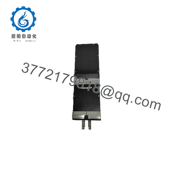
FBM02
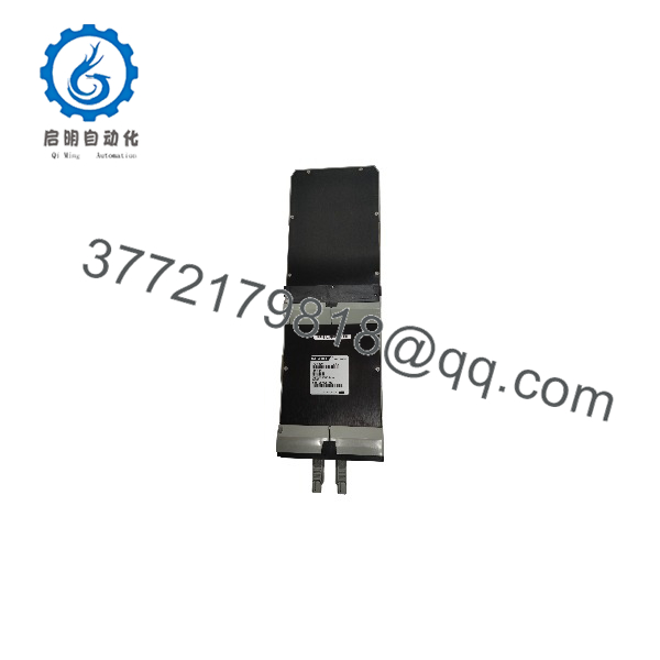
FBM02
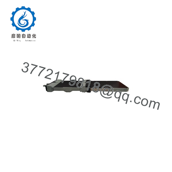
FBM02
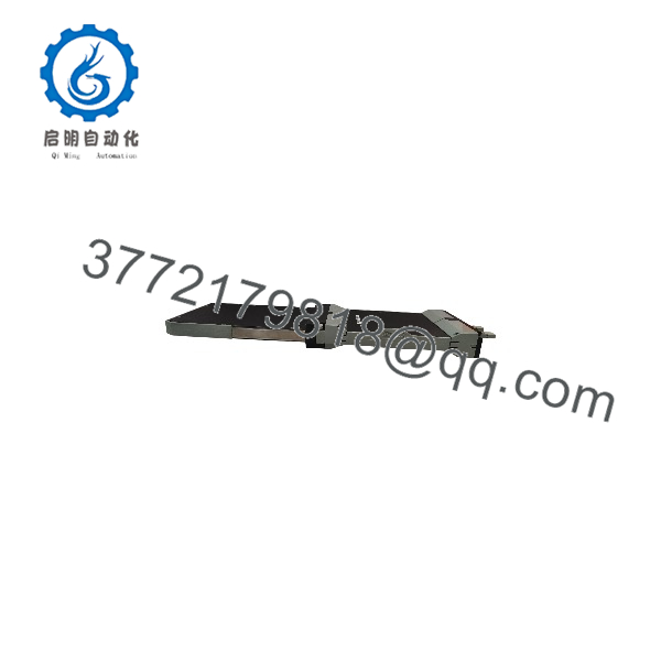
FBM02
Firmware/Software Versions & Upgrade Notes
- Software Compatibility: The FBM02 interfaces directly with Foxboro I/A Series software letter bugs (including System Software v4.x, v6.x, and v8.x).
- System Integration: When replacing legacy 100 Series cards or migrating toward 200 Series architecture (such as FBM202), verify whether your Termination Assemblies (TAs) require 100-to-200 Series conversion cables or updated block configuration parameters.
- Configuration Retention: Analog input resolution and software integration periods are set via the I/A Series Control Processor software configuration; no internal module EEPROM re-flashing is required during hardware replacements.
Frequently Asked Questions (FAQ)
This product is listed as New Surplus. Is it a used or refurbished card?
This product is a Brand New Surplus unit. It is not used, not pulled from a decommissioned plant, and not refurbished. All modules undergo rigorous quality verification to ensure OEM-level reliability.
Why should our plant choose New Surplus modules over cheaper refurbished options?
Refurbished DCS cards often suffer from aged isolation transformers and worn backplane contacts, which can cause erratic thermal readings. Saving $400 on a refurbished module can lead to tens of thousands of dollars in downtime if a false burnout signal triggers a boiler or reactor trip.
What is the primary difference between the 100 Series and the 200 Series FBM202?
The belongs to the legacy 100 Series form factor using rack-mount enclosures and ribbon-cable termination blocks. The FBM202 is the compact 200 Series equivalent designed for DIN-rail baseplates. Functionally, both process 8 thermocouple/mV channels, but physical mounting and baseplates differ.
How does cold junction compensation (CJC) work on the ?
Cold junction compensation is provided by a 100 Ω platinum RTD built directly into the field termination assembly (or connected as a 4-wire RTD). The dedicates an isolated 9th channel to measure reference temperature and apply accurate software offset math to thermocouple mV inputs.
Can I pull or replace the module while the DCS rack is powered on?
While some Foxboro I/A hardware supports live swapping, it is recommended to isolate field power and verify cabinet grounding before removing legacy 100 Series modules to prevent transient signal faults on adjacent thermocouple channels.
What warranty comes with this FOXBORO module?
All New Surplus FOXBORO modules come with a full 1-year replacement warranty, accompanied by serial verification and complete QC inspection documentation.



