
 WhatsApp: +86 16626708626
 Email:
  Phone: +86 16626708626
Description
Key Technical Specifications
| Parameter | Value |
|---|---|
| Manufacturer | Foxboro (Schneider Electric) |
| Product Model | FBM02 |
| Product Family | I/A Series 100 Series FBM |
| Product Type | Thermocouple/mV Input Interface Module |
| Input Channels | 8 isolated thermocouple/mV channels |
| Reference Junction | 1 isolated RTD compensation channel |
| Supported Sensors | Standard thermocouple types and millivolt inputs |
| Communication | Redundant Foxboro Fieldbus |
| Isolation | Channel-to-channel and channel-to-ground isolation |
| Application Program | Analog Input |
| Installation | DIN rail or Fieldbus baseplate |
| Typical Application | Temperature measurement in process automation |
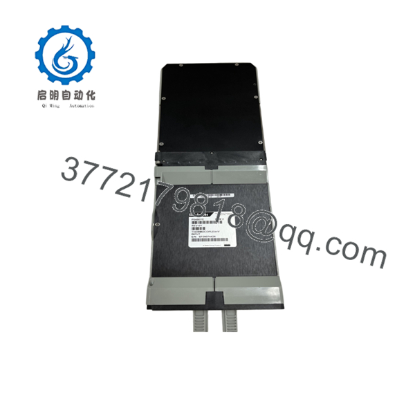
The FBM02 provides eight isolated thermocouple or millivolt input channels plus an isolated reference junction compensation channel. It performs signal conversion and communicates measured values over the redundant Foxboro Fieldbus to the I/A Series control system.
Product Introduction
The Foxboro FBM02 is an analog input interface module developed for the Foxboro I/A Series Distributed Control System. It is dedicated to temperature measurement using thermocouples and low-level millivolt sensors in demanding industrial environments. The module executes the Analog Input application program and supports configurable integration times to balance response speed and noise rejection.
Each of the eight measurement channels is electrically isolated, reducing the risk of ground-loop interference. An additional RTD channel provides automatic cold-junction compensation, improving thermocouple measurement accuracy without requiring an external reference sensor.
Installation & Configuration Guide
Stage 1 – Pre-Installation Preparation (10 Minutes)
⚠️ Safety First
- Notify operations before beginning maintenance.
- Perform Lock-Out/Tag-Out procedures.
- Remove Fieldbus power.
- Wear a grounded ESD wrist strap.
Required Tools
- Digital multimeter
- Small Phillips screwdriver
- ESD wrist strap
- Wire identification labels
- Thermocouple simulator (recommended)
Before Removal
- Back up the I/A Series database.
- Record channel configuration.
- Photograph all terminal wiring.
- Identify each thermocouple type before disconnecting wiring.
Stage 2 – Removing the Existing Module (5 Minutes)
- Disconnect Fieldbus power.
- Label every thermocouple lead.
- Remove the terminal assembly carefully.
- Release the module locking mechanism.
- Remove the FBM02 straight from the baseplate.
⚠️ Never mix thermocouple extension wire types during replacement. Incorrect extension wire introduces measurement errors that calibration cannot correct.
Stage 3 – Installing the New Module (10 Minutes)
- Verify the replacement is Foxboro FBM02.
- Install the module firmly onto the Fieldbus baseplate.
- Reconnect all thermocouple wiring according to the original documentation.
- Verify polarity for every channel.
- Confirm proper grounding and shielding practices.
Installation Checklist
- ✔ Correct module installed
- ✔ Thermocouple polarity verified
- ✔ Shield grounding confirmed
- ✔ Module securely seated
Stage 4 – Power-Up & Commissioning (15 Minutes)
- Restore Fieldbus power.
- Verify normal module status indicators.
- Download or verify the existing configuration.
- Check cold-junction compensation readings.
- Simulate several temperature points.
- Confirm alarm limits and engineering units.
- Record commissioning results.
⚠️ If every channel shows similar temperature offsets, inspect the reference junction compensation channel before replacing the module. Field wiring and ambient terminal conditions are often the real source of the error.

- FBM02
Frequently Asked Questions (FAQ)
Q1. What signals does the accept?
The accepts standard thermocouple inputs and low-level millivolt signals. It is intended for temperature measurement applications throughout the Foxboro I/A Series DCS.
Q2. How many input channels are available?
The module provides:
- 8 isolated thermocouple/mV input channels
- 1 isolated RTD reference junction compensation channel
This design improves measurement accuracy by automatically compensating for terminal temperature.
Q3. Is the still manufactured?
The 100 Series FBMs, including the , are legacy products. Many systems remain in operation, but new production is limited. Most replacement demand is met through new surplus inventory or professionally tested refurbished units.
Q4. Can the be replaced by the FBM202?
Yes. In many Foxboro Evo migrations, the FBM202 is used as the functional successor to the . Appropriate termination assemblies are available to support migration from the 100 Series architecture. Compatibility should be verified before installation.
Q5. Why is cold-junction compensation important?
Thermocouples measure temperature differences rather than absolute temperature. The uses an integrated RTD reference junction channel to compensate for terminal temperature, improving overall measurement accuracy.
Q6. Can the module be hot-swapped?
No. De-energizing the Fieldbus before replacing the module is recommended. Removing an FBM under power can interrupt communications and increase the risk of configuration or hardware issues.
Q7. What industries commonly use the ?
Typical installations include:
- Oil and gas
- Petrochemical plants
- Power generation
- Chemical processing
- Pulp and paper
- Pharmaceutical manufacturing
- Water and wastewater treatment
These applications rely on accurate temperature monitoring for process control and equipment protection.



