
 WhatsApp: +86 16626708626
 Email:
  Phone: +86 16626708626
Description
Key Technical Specifications
| Parameter | Specification Value |
| Channel Capacity | 8 isolated and independent input channels |
| Supported Sensor Types | Platinum (100 Ω nominal at 0 °C) and Nickel (235 Ω nominal at 0 °C) |
| Wiring Configurations | 2-wire, 3-wire, or 4-wire variable-resistance RTDs (cannot mix 3-wire with 2/4-wire on same card) |
| Input Resistance Range | 0 to 320 Ω |
| Sensor Excitation Current | 0.75 mA DC |
| Accuracy | ±0.025% of span (±0.08 Ω) |
| Conformity | ±0.25 °C |
| Power Requirements | 26 to 42 V DC redundant input range |
| Power Consumption / Heat Dissipation | 9 W maximum |
| Channel Isolation | 600 V AC for 1 minute between channels, or channel-to-earth ground |
| Operating Temperature | 0 °C to +60 °C (32 °F to +140 °F) |
| Module Mass | 1.0 kg (2.2 lb) |
Product Introduction & Supply Chain Strategy
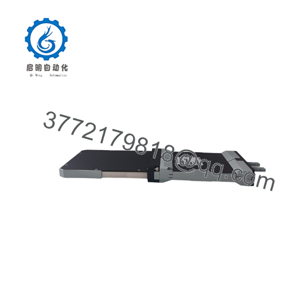
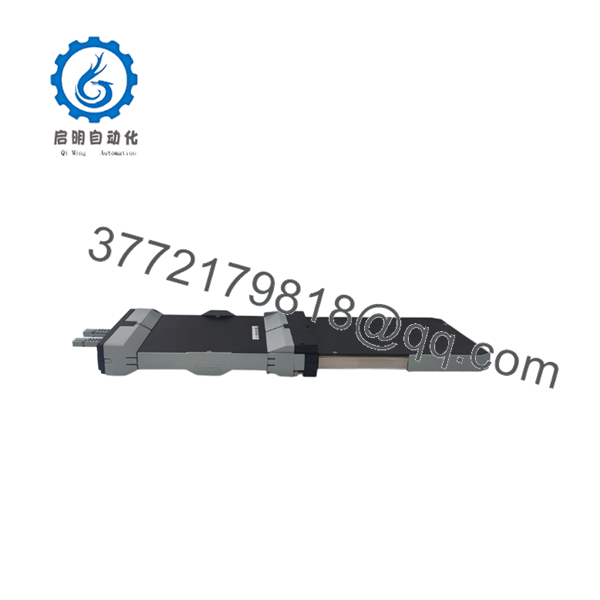
The Foxboro FBM03 (P0400YD) is an 8-channel RTD input interface module engineered for the Foxboro I/A Series Distributed Control System (DCS). It converts resistance measurements from 2-, 3-, or 4-wire Platinum and Nickel RTD sensors into temperature data transmitted across the redundant Fieldbus network to process control processors.
Because legacy 100 Series Fieldbus Modules are discontinued by the OEM, securing this unit as a New Surplus capital spare protects process lines against sudden single-point DCS failures. Procuring genuine New Surplus avoids degraded electrolytic power circuitry and stressed optocouplers common in secondhand pulls, preserving system availability and maintaining a low total cost of ownership (TCO).
Installation & Configuration Guide
Stage 1: Pre-Installation (Prep & Safety)
- Perform lockout/tagout procedures on field temperature loop output interlocks.
- Put on an ESD-grounded wrist strap before handling the replacement module.
- Open the I/A Series System Engineering Software (ICC/IACC) and back up the current station environment file.
- Document terminal wiring blocks, channel allocation, and check whether 2-, 3-, or 4-wire RTD jumpers are deployed on the associated termination block.
Stage 2: Removal
- Disconnect or unlatch fieldbus cable connections from the module faceplate/baseplate structure.
- Loosen the retention screws securing the card to the mounting rack.
- Carefully pull the module straight out along its guide tracks to avoid bending backplane contacts, placing it directly into an ESD-shielded pouch.
Stage 3: Installation (Clone & Seat)
- Verify the replacement FBM03 module hardware revision matches the pulled module.
- Align the module circuit board with the guide slots in the 1×8 or 2×8 FBM mounting structure.
- Push the card in firmly until the rear backplane connectors seat completely, then tighten all mounting screws.
Stage 4: Power-On & Testing
- Restore 26–42 V DC power to the fieldbus mounting baseplate.
- Check front-panel status LEDs to ensure proper backplane power-on self-test and active fieldbus communication.
- Measure live RTD loop values in system diagnostics software using a decade resistance box to verify 0 to 320 Ω scaling accuracy before releasing loop holds.

- FBM03
- FBM03
Firmware/Software Versions & Upgrade Notes
- System Compatibility: Compatible with Foxboro I/A Series system software (version 4.x/6.x/8.x) managing 100 Series Fieldbus Modules.
- Configuration Notice: Configured via the Analog Input (AIN) software block in I/A Series software. Resolution, conversion time, and fieldbus switching parameters must be defined on a per-module basis.
- Mixed Sensor Restrictions: While individual channels measure 0 to 320 Ω, 3-wire RTDs cannot be mixed with 2- or 4-wire RTDs on the same FBM03 card. Attempting to combine 3-wire and 2/4-wire field sensors on one module will cause resistance measurement offsets and trigger signal fault flags.
Frequently Asked Questions (FAQ)
What is the difference between part number FBM03 and P0400YD?
is the model designation for the Platinum and Nickel RTD Input Module. P0400YD is the exact Foxboro OEM manufacturing part number printed on the module chassis.
Is this Foxboro module guaranteed to be brand new surplus?
Yes. Every unit supplied is 100% Brand New Surplus sourced from verified global inventories. The cards sit in anti-static packaging, show zero backplane edge connector insertion wear, and pass full functional QC testing.
Why choose New Surplus over low-cost refurbished I/A Series modules?
Refurbished legacy cards often suffer from heat-stressed power regulation circuits and aging input optocouplers after years of continuous operation inside control cabinets. Spending 20% to 30% more for a New Surplus card provides original factory insulation properties (600 V AC isolation rating) and protects against multi-thousand-dollar unscheduled process shutdowns.
Can I hot-swap this module while the DCS is powered?
Yes. The is designed for live insertion and removal on powered I/A Series mounting structures. However, you must software-inhibit or bypass the associated AIN blocks to prevent control loops from taking action on transient signal drops during physical extraction.
Does replacing the require re-downloading system software?
No full system rebuild is needed. When placed onto the fieldbus baseplate, the accepts software parameter downloads (conversion rate, resolution) directly from the active Control Processor (CP).
What warranty coverage is included with this unit?
All New Surplus Foxboro modules include a full 1-year replacement warranty, serial number verification, and a comprehensive pre-shipment functional test certificate.



