
 WhatsApp: +86 16626708626
 Email:
  Phone: +86 16626708626
Description
Key Technical Specifications
| Parameter | Value |
|---|---|
| Product Model | FBM07 |
| Manufacturer | Foxboro |
| System Platform | I/A Series DCS |
| Product Type | Contact/DC Input Interface Module |
| Input Channels | 16 independent digital input channels |
| Signal Type | Dry contact input or DC voltage monitoring |
| Communication | Redundant I/A Series Fieldbus |
| Input Filter Time | 4 ms, 8 ms, 16 ms, or 32 ms configurable |
| Input Voltage Range | Contact sensing / 15 to 130 V DC voltage monitoring |
| Contact Open Voltage | 24 V DC ±10 % |
| Short Circuit Current | 2.5 mA maximum |
| ON-State Resistance | 1 kΩ maximum |
| OFF-State Resistance | 100 kΩ minimum |
| Supply Voltage | 26 to 42 V DC redundant input |
| Power Consumption | 7 W maximum (main module only) |
| Heat Dissipation | 12 W maximum (main module only) |
| Operating Temperature | 0 to 60 °C |
| Storage Temperature | −40 to +70 °C |
| Humidity Range | 5 to 95 % RH, non-condensing |
| Mounting | I/A Series FBM mounting structures |
| Weight | Approximately 1 kg |
The Foxboro FBM07 is an I/A Series Contact/DC Input Interface Module designed for 16-channel discrete field signal acquisition. It converts contact states or DC voltage signals from field devices into digital data transmitted through the redundant Fieldbus network.
Product Introduction
The Foxboro FBM07 is a 16-channel digital input Fieldbus Module used in Foxboro I/A Series distributed control systems. It interfaces field switches, relay contacts, and DC status signals with the DCS control network. Typical applications include motor status monitoring, valve feedback, alarm inputs, and sequence-of-events monitoring.
The module supports configurable input filtering and redundant Fieldbus communication. In legacy I/A Series installations, engineers select FBM07 replacements carefully because termination assemblies, field voltage types, and module variants must match the existing application.
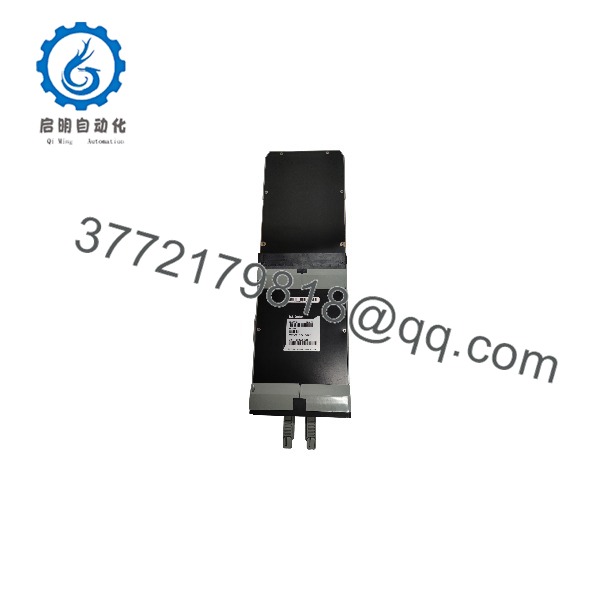
FBM07
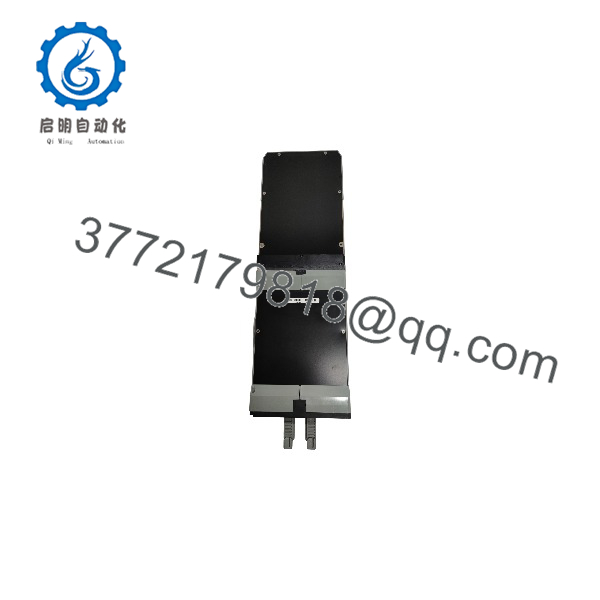
FBM07
Installation & Configuration Guide
Stage 1: Pre-Installation Preparation (Approx. 10 minutes)
⚠️ Safety First
- Notify operations before taking the I/A Series rack offline.
- Confirm the affected control loop or interlock can safely be bypassed.
- Apply lockout/tagout procedures where required.
- Remove module power and wait at least 5 minutes before handling connections.
Tools Required
- ESD wrist strap
- PH1 screwdriver
- Digital multimeter
- Wire labels
- Smartphone for photos
Data Backup
Before removing the old FBM07:
- Record the exact module part number and revision.
- Photograph terminal block wiring.
- Record channel assignments from the DCS configuration database.
- Document Fieldbus address and module position.
- Save current I/O configuration files if available.
Stage 2: Removing the Old Module (Approx. 10 minutes)
Steps
- Open the I/A Series cabinet access panel.
- Confirm the correct FBM07 location.
- Label each field wire before removal.
- Disconnect the field termination wiring carefully.
- Release the module retaining mechanism.
- Pull the straight out from the mounting assembly.
- Inspect the backplane connector for dust, corrosion, or bent contacts.
⚠️ Note:
Keep the original installed until the replacement configuration has been verified. Older I/A Series systems often depend on exact module addressing and termination arrangements.
Stage 3: Installing the New Module (Approx. 10 minutes)
Steps
- Wear an ESD strap before touching the replacement .
- Verify:
- Model =
- Correct revision
- Correct termination assembly compatibility
- Configuration Clone (Critical):
- Match module position.
- Confirm channel assignment.
- Verify input signal type.
- Copy filtering parameters.
- Check Fieldbus configuration.
- Insert the module into the mounting position.
- Secure the module locking mechanism.
- Reconnect field wiring using the original labels.
Self-Checklist
- Correct installed
- Termination block verified
- Field wiring secured
- Module locked in position
- Configuration matches original
Stage 4: Power-On & Testing (Approx. 15 minutes)
Pre-Power Check
- Verify field wiring polarity.
- Check DC input voltage using a multimeter.
- Confirm no short circuit exists between field terminals.
Power-On Steps
- Restore rack power.
- Observe FBM status LEDs.
- Confirm Fieldbus communication.
- Check module health status in the I/A Series workstation.
- Verify all 16 input channels.
- Perform field device simulation testing.
⚠️ Troubleshooting Note
- If the module does not communicate, check Fieldbus addressing and termination.
- If input states are incorrect, verify contact/DC voltage configuration.
- If signals change slowly, check input filter settings.
Frequently Asked Questions (FAQ)
Q1: Can the Foxboro be hot-swapped?
It depends on the I/A Series hardware configuration. Some Foxboro FBM architectures support online replacement procedures, but the exact method depends on the cabinet design, termination hardware, and system revision. Verify the site maintenance procedure before removing any module under power.
Q2: Is the Foxboro obsolete?
The belongs to the mature Foxboro I/A Series product family. Many plants still operate I/A Series systems, so replacement demand remains. However, availability is mainly based on existing inventory and surplus stock channels.
Q3: What is the difference between and FBM08?
They are both Foxboro I/A Series digital input modules, but the field signal types differ.
- Contact/DC input interface
- FBM08: 120 V AC input interface
Installing the wrong module can create incorrect field signal interpretation. Always check the original engineering drawings before replacement.
Q4: Will replacing an erase my DCS configuration?
No. The I/O database and control strategy are stored in the I/A Series control system, not inside the input electronics alone. However, the replacement module must match the configured I/O type, address, and termination arrangement.
Q5: Why is a surplus Foxboro cheaper than a new OEM module?
Legacy DCS spare parts often enter the market through excess plant inventory, project cancellations, panel-builder stock, or equipment retirement programs.
Before purchase, confirm the condition:
- New Original / New Surplus: Unused module from inventory.
- Factory Sealed: Original unopened packaging when available.
- Refurbished (tested): Inspected and function-tested before shipment.
Q6: What inspection process should be completed before installing a used ?
A proper inspection process should include:
1. Inbound Inspection & Traceability
- Verify supplier records and packing documentation.
- Check serial number and module labels.
- Inspect enclosure condition.
- Confirm no corrosion, scratches, repair marks, or contamination.
- Audit included accessories.
2. Live Functional Testing
Test environment:
- Genuine Foxboro I/A Series test rack.
Testing steps:
- Power-up LED verification.
- Fieldbus communication check.
- Digital input simulation.
- Channel status verification.
- Continuous operation monitoring.
- Test report generation.
3. Electrical Parameter Testing
- Insulation resistance testing where applicable.
- Ground continuity verification.
- Input channel electrical checks.
4. Configuration Verification
- Record hardware revision.
- Document module settings.
- Save configuration records.
5. Final QC & Packaging
- QC inspector approval.
- Anti-static ESD bagging.
- Protective bubble wrap.
- Heavy-duty packaging.
- QC label with inspection date.
Q7: What are the most common replacement mistakes?
❗ The most common mistake is ordering the correct-looking module with the wrong field interface requirement.
I have seen I/A Series replacements delayed because a team matched the model number but ignored the termination assembly and field voltage type.
Common problems include:
- Confusing with AC input modules.
- Mixing contact sensing and DC voltage monitoring applications.
- Forgetting input filter settings.
- Incorrect Fieldbus addressing.
- Damaging connectors through forced installation.
Take photos before removal. Verify the engineering database. Those two checks prevent most replacement delays during legacy DCS maintenance.



