
 WhatsApp: +86 16626708626
 Email:
  Phone: +86 16626708626
Description
Key Technical Specifications
| Parameter | Value |
|---|---|
| Manufacturer | Foxboro (Schneider Electric) |
| Product Model | FBM07 |
| Product Family | I/A Series 100 Series FBM |
| Product Type | Contact/DC Input Interface Module |
| Input Channels | 16 Digital Inputs |
| Supported Input Types | Dry Contact or DC Voltage Monitoring |
| Input Voltage Range | 15–130 VDC (voltage monitor version) |
| Contact Wetting Voltage | 24 VDC (contact sense version) |
| Communication | Redundant Foxboro Fieldbus |
| Expansion Capability | Supports one FBM12 Expansion Module (32 total inputs) |
| Isolation | Channel-pair isolation and ground isolation |
| Typical Applications | Digital Status Monitoring, Sequence of Events (SOE), Pulse Counting |
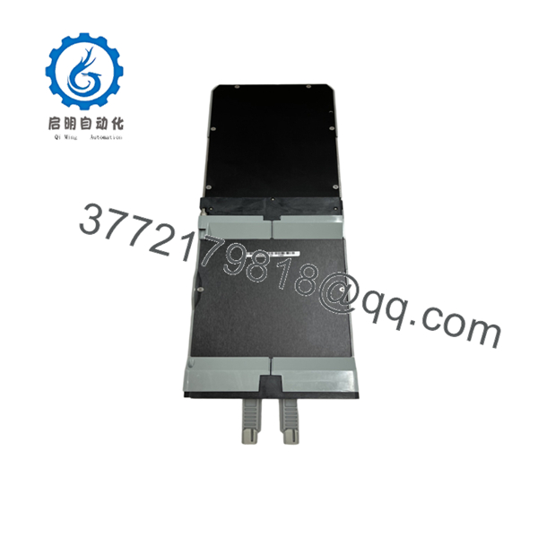
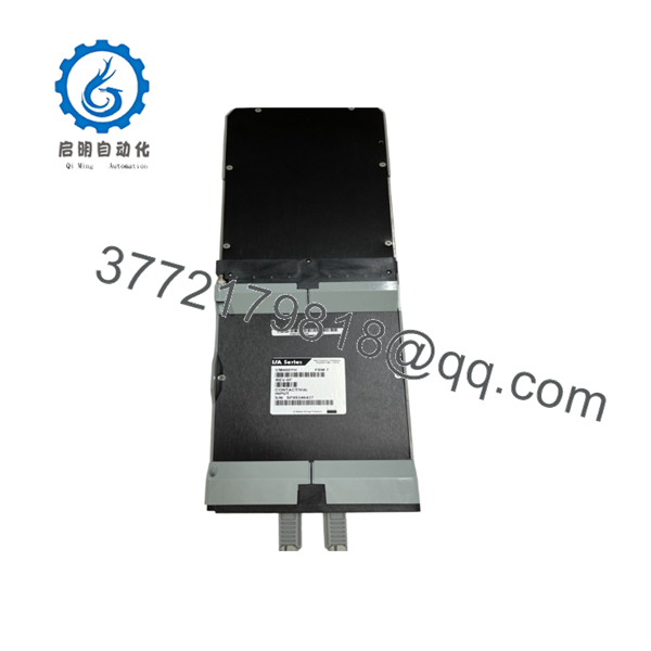
The FBM07 is an expandable digital input interface module that independently connects to the Foxboro redundant Fieldbus. It functions as a 16-channel contact sensor or DC voltage monitor and can be paired with an FBM12 Expansion Module to increase capacity to 32 input channels.
Product Introduction
The Foxboro FBM07 is a digital input interface module designed for the Foxboro I/A Series Distributed Control System (DCS). It converts field contact and DC voltage signals into digital data for use by the control processor. The module supports Digital I/O, Sequence of Events (SOE), Pulse Count, and Ladder Logic applications, making it suitable for both standard monitoring and high-speed event recording.
One of the major advantages of the FBM07 is its expandability. A single FBM07 can support one FBM12 Expansion Module, allowing engineers to double the available digital input capacity without adding another Fieldbus connection. This approach reduces cabinet space and simplifies system expansion.

- FBM07
Installation & Configuration Guide
Stage 1 – Pre-Installation Preparation (10 Minutes)
⚠️ Safety First
- Notify plant operations of scheduled maintenance.
- Perform Lock-Out/Tag-Out procedures.
- Isolate Fieldbus power.
- Wear an ESD wrist strap before handling the module.
Required Tools
- Digital multimeter
- Phillips screwdriver
- ESD wrist strap
- Wire labels
- Portable voltage source for input verification
Before Removal
- Back up the I/A Series configuration.
- Record channel assignments.
- Photograph terminal wiring.
- Verify whether the installation uses Contact Sense or Voltage Monitor inputs.
Stage 2 – Remove Existing Module (5 Minutes)
- Disconnect Fieldbus power.
- Label every field cable.
- Remove the terminal assembly.
- Release the retaining mechanism.
- Remove the from the mounting base.
⚠️ If an FBM12 Expansion Module is installed, disconnect it only after documenting the expansion wiring.
Stage 3 – Install the New Module (10 Minutes)
- Verify the replacement model is .
- Install the module onto the Fieldbus baseplate.
- Reconnect all field wiring.
- If applicable, reconnect the FBM12 Expansion Module.
- Verify wiring polarity and grounding.
- Confirm the module is fully seated.
Installation Checklist
- ✔ Correct FBM installed
- ✔ Wiring restored
- ✔ Expansion module connected
- ✔ Module securely locked
Stage 4 – Commissioning (15 Minutes)
- Restore Fieldbus power.
- Verify module status LEDs.
- Download or verify the existing configuration.
- Test every digital input.
- Verify SOE or Pulse Count functions if configured.
- Record commissioning results.
⚠️ If multiple inputs remain permanently ON or OFF, inspect the external wiring and field power supply before replacing the module. Most field failures originate from wiring faults or incorrect input voltage rather than FBM hardware.
Frequently Asked Questions (FAQ)
Q1. What does the do?
The converts digital contact or DC voltage signals from field devices into data that the Foxboro I/A Series DCS can process. It supports digital status monitoring, Sequence of Events (SOE), Pulse Count, and Ladder Logic applications.
Q2. How many input channels are available?
The provides 16 digital input channels. When paired with an FBM12 Expansion Module, the system supports 32 total input channels through a single Fieldbus connection.
Q3. What input signals are supported?
Depending on the hardware version, the supports:
- Dry contact sensing
- 15–130 VDC voltage monitoring
- Pulse count inputs
- Sequence of Events (SOE) monitoring
Q4. Can the be expanded?
Yes. One Expansion Input Interface Module can be connected to an , increasing capacity from 16 to 32 digital inputs without requiring another primary Fieldbus connection.
Q5. Is the still available?
The is a legacy 100 Series module. While it is no longer a current-generation product, replacement units remain available as new surplus, unused inventory, or professionally tested refurbished modules.
Q6. Can the be replaced by a newer module?
For Foxboro Evo migration projects, the FBM207 Series is commonly used as the successor platform. However, replacement requires compatible termination assemblies and verification of the control strategy before installation.
Q7. Which industries commonly use the ?
Typical applications include:
- Oil and gas
- Petrochemical processing
- Power generation
- Chemical manufacturing
- Water and wastewater treatment
- Pulp and paper
- General industrial automation
These facilities use the for digital equipment status monitoring, alarm handling, interlocks, and sequence-of-events recording within Foxboro I/A Series DCS installations.



