
 WhatsApp: +86 16626708626
 Email:
  Phone: +86 16626708626
Description
Key Technical Specifications
| Parameter | Specification |
| Manufacturer | FOXBORO / Invensys / Schneider Electric |
| Model / Part Number | FBM09 / P0400YK |
| Input Channels | 4 analog input channels |
| Input Signal Range | 0 to 20 mA DC (configurable for 4 to 20 mA DC) |
| Output Channels | 4 analog output channels |
| Output Signal Range | 0 to 20 mA DC (supports 4 to 20 mA DC positioners/actuators) |
| Resolution / Conversion | 12-bit A/D (Inputs) and 12-bit D/A (Outputs) |
| Input Impedance | 250 Ω nominal |
| Output Load Resistance | 0 to 750 Ω maximum load |
| Channel Isolation | Galvanic isolation (channel-to-earth & channel-to-bus, 600 V AC withstand) |
| Operating Voltage | 26 to 42 V DC (redundant bus power from baseplate) |
| Power Dissipation | 12 W maximum |
| Operating Temperature | 0 to 60°C (32 to 140°F) |
Product Introduction & Supply Chain Strategy
The FOXBORO FBM09 (P0400YK) is a versatile combination 4-input / 4-output analog module engineered for Foxboro I/A Series Distributed Control Systems (DCS). It processes four 0–20 mA current signals from field transmitters while simultaneously driving four 0–20 mA control loops to final control elements such as control valves, variable frequency drives (VFDs), and dampers.
Because the legacy 100 Series architecture is fully factory-discontinued, maintaining New Surplus FBM09 stock on-site is an essential risk-mitigation strategy. Securing factory-fresh, zero-hour units eliminates the high failure rate and loop drift common in worn, refurbished cards—protecting continuous process operations from costly unscheduled downtime.
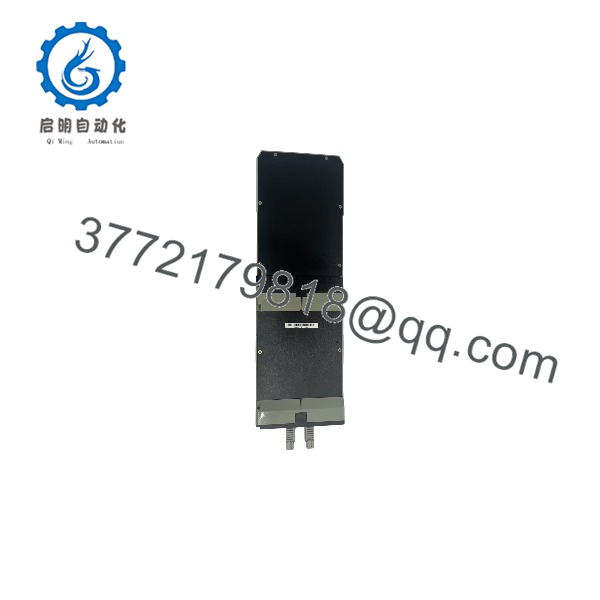
FBM09
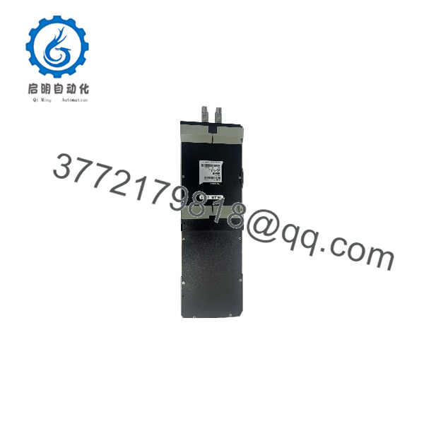
FBM09
Installation & Configuration Guide
Stage 1: Pre-Installation (Prep & Safety)
- Perform Lock-Out/Tag-Out (LOTO) procedures on connected field power loops and control cabinet power rails.
- Wear an ESD wrist strap connected to a solid panel earth ground to protect sensitive A/D and D/A converter circuits.
- Document side-panel DIP switch settings (Node Address and Fieldbus baud rate) and take a reference photo of the field terminal block wiring.
Stage 2: Removal
- Unfasten the top and bottom captive retaining screws securing the old FBM09 to the mounting baseplate.
- Carefully pull the module straight out along its guide rails to prevent twisting or bending the backplane pin assembly.
- Inspect the backplane connector for dust, debris, or oxidation prior to installing the new unit.
Stage 3: Installation (Clone & Seat)
- Verify that the DIP switch configuration on the New Surplus FBM09 exactly matches the original module parameters.
- Align the module card edges with the backplane slots and press firmly until the backplane connector fully seats.
- Hand-tighten the retaining screws to lock the card securely into the rack frame.
Stage 4: Power-On & Testing
- Re-apply system power to the rack chassis bus.
- Confirm that the front-panel green RUN LED illuminates steady and the red ERR LED turns off after the power-on boot check.
- Check 4–20 mA transmitter values and output command signals on the Foxboro Workstation display to verify analog accuracy.
Firmware/Software Versions & Upgrade Notes
- Software Compatibility: The FBM09 integrates seamlessly with Foxboro I/A Series System Software versions (including v4.x, v6.x, and v8.x).
- System Integration: When replacing or expanding loops, confirm block definition parameters in your I/A Series Compound/Block configuration (such as
AINandAOTblock types). - Migration Paths: If upgrading from 100 Series to 200 Series DIN-rail hardware (e.g., FBM201 / FBM204), migration cables and baseplate adapters are required to adapt existing field wiring termination assemblies (TAs).
Frequently Asked Questions (FAQ)
Is this FOXBORO module a new original unit or a refurbished pull?
This product is a Brand New Surplus unit. It is not used, not pulled from a decommissioned plant, and not refurbished. All modules undergo rigorous quality verification to ensure OEM-level reliability.
Why is New Surplus a better procurement choice than a cheaper refurbished ?
Refurbished analog cards often contain aging electrolytic capacitors and worn D/A output stages susceptible to thermal drift or sudden component shorting. An unexpected failure on an analog output loop driving a critical control valve can cost tens of thousands of dollars in off-spec production or emergency plant shutdowns.
What is the benefit of a combination input/output card like the ?
The consolidates 4 analog inputs and 4 analog outputs into a single card slot. This maximizes rack space efficiency on smaller legacy I/A Series baseplates while providing fully isolated input/output signal processing.
Can I configure individual channels for 4–20 mA instead of 0–20 mA?
Yes. The physical hardware processes 0 to 20 mA full-scale signals (0 to 65,535 counts), while the 4 to 20 mA range is defined via software scaling (e.g., 20% elevation) within the Foxboro I/A Series control software.
Is the hot-swappable while the system rail is energized?
While Foxboro I/A Series backplanes are designed with fieldbus protection, best engineering practices dictate isolating field loop power or putting associated control loops in MANUAL mode before replacing hardware to prevent transient bumps to active process valves.
What warranty comes with this New Surplus card?
Every New Surplus FOXBORO module includes a full 1-year replacement warranty, accompanied by serial verification and complete pre-shipment quality inspection reports.



