
 WhatsApp: +86 16626708626
 Email:
  Phone: +86 16626708626
Description
Key Technical Specifications
| Parameter | Value |
|---|---|
| Manufacturer | Foxboro, formerly Invensys Process Systems; now part of Schneider Electric |
| Module designation | FBM12 |
| Common part number | CM400YN |
| Product family | Foxboro I/A Series 100 Series Fieldbus Modules |
| Product type | Contact/DC Expansion Input Interface Module |
| Main module relationship | Expansion module used with FBM07 contact/DC input main module |
| Input channels | 16 independent digital input channels |
| Input functions | Contact sensor input or DC voltage-monitor input |
| Contact-sensor open-circuit voltage | 24 V DC ±10% |
| Contact-sensor short-circuit current | 2.5 mA maximum |
| DC voltage-monitor ON-state range | 15–130 V DC |
| DC voltage-monitor OFF-state range | 0–5 V DC |
| Input filter time | Configurable: 4, 8, 16, or 32 ms |
| Channel isolation | Inputs isolated in pairs; each pair shares a common return |
| Input-to-ground isolation withstand | 1,250 V AC for 1 minute |
| Pair-to-pair isolation withstand | 1,250 V AC for 1 minute |
| Fieldbus supply range | 26–42 V DC through the redundant fieldbus; FBM12 is used with an FBM07 main module |
| Main + expansion power consumption | 12 W maximum |
| Main + expansion heat dissipation | 22 W maximum |
| Operating temperature | 0 to 60 °C (32 to 140 °F) |
| Storage temperature | −40 to +70 °C (−40 to +158 °F) |
| Relative humidity | 5–95%, noncondensing |
| Industrial environmental classification | ISA S71.04 Class G3 harsh environment |
| Field termination options | Discrete-wire screw terminals or 34-pin plug connector, depending on the termination assembly |
The Foxboro FBM12 is an expansion input module, not a standalone fieldbus module. It provides 16 contact or DC voltage-monitor inputs and communicates through the associated FBM07 main module. The original I/A Series product specification states that the input configuration is made on a per-module basis and identifies four selectable input-filter times: 4, 8, 16, and 32 ms.
Product Introduction
The Foxboro FBM12, commonly marked CM400YN, is a 16-channel contact/DC input expansion interface module for legacy Foxboro I/A Series DCS systems. It increases discrete input capacity for field contacts, relay status signals, pushbuttons, limit switches, permissive circuits, and DC voltage-status monitoring.
The FBM12 works with an FBM07 main module and does not provide independent fieldbus communication. That detail matters during replacement: a healthy FBM12 can appear failed when the paired FBM07, Y-adapter, fieldbus supply, terminal assembly, or common input return is the actual problem.
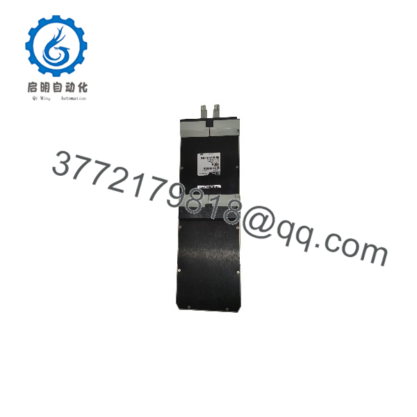
FBM12
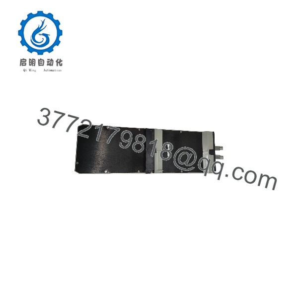
FBM12
Troubleshooting Quick Reference
| Symptom | Possible Cause | Relevance to This Part | Quick Check Method | Recommendation |
|---|---|---|---|---|
| All 16 input points are unavailable | FBM07 main module failed, fieldbus supply loss, Y-adapter issue, loose expansion connection, failed | ✅ High | Check operational status first. Confirm 26–42 V DC redundant fieldbus supply at the mounting structure. Power down under approved procedure and inspect the -to-/Y-adapter connection. | Do not replace the until the associated and fieldbus supply are confirmed healthy. |
| One input remains OFF with field device energized | Open conductor, failed contact, wrong common return, insufficient field voltage, failed channel | ⚠️ Medium | Measure voltage at the exact terminal pair. For DC monitor wiring, verify 15–130 V DC at the input for an ON state. For contact-sensor wiring, check continuity and confirm the module supplies approximately 24 V DC open circuit. | Repair field wiring, contact hardware, or common-return faults before replacing the module. |
| One input remains ON after field contact opens | Shorted cable, welded relay contact, moisture ingress, incorrect field wiring, failed input channel | ⚠️ Medium | Disconnect the field conductor at the terminal assembly. If the DCS point stays ON with field wiring removed, inspect the terminal assembly and input channel. If it changes OFF, troubleshoot the external circuit. | Trace the cable and field contact first. Replace only when the input remains incorrect with proven field isolation. |
| Several adjacent inputs fail together | Shared return fault, terminal assembly damage, broken cable harness, field power loss | ⚠️ Medium | Identify the affected channel pairs and inspect their shared common-return wiring. Measure the common reference at the terminal assembly. Check for loosened screw terminals or discoloration. | Repair the common-return or terminal issue before replacing the module. Inputs are isolated in pairs and each pair shares a common return. |
| Input status flickers or chatters | Contact bounce, electrical noise, damaged shielding, poor grounding, filter time too short | ⚠️ Medium | Trend the point at high resolution. Inspect the actual field contact with a meter or scope. Confirm the configured filter is appropriate: 4, 8, 16, or 32 ms. | Increase filtering only after confirming the field device does not require fast response. Fix noise and grounding faults at the source. |
| DCS shows incorrect status after an swap | Wrong FBM type, incorrect module configuration, terminal block transferred incorrectly, paired not recognized | ✅ High | Compare the removed and replacement labels: and CM400YN. Confirm the I/A Series database expects an expansion input module at that position. Verify terminal assembly part number and cable orientation. | Restore the correct configuration and recheck every field terminal against the wiring drawing. Do not wire from memory. |
| Status LEDs do not match field signals | Field wiring reversed, wrong contact/DC monitor configuration, module filter delay, terminal assembly mismatch | ⚠️ Medium | Compare terminal voltage and DCS status point-by-point. Verify whether the module is configured for contact-sensor or DC voltage-monitor service. Check the selected filter delay. | Correct configuration and terminal wiring before replacing hardware. |
| Module or terminal area overheats | Loose field terminal, excessive voltage applied, wrong supply connection, cabinet heat issue, damaged module | ✅ High | Isolate power immediately if safe to do so. Inspect for odor, heat discoloration, melted insulation, or loose terminals. Measure input voltage; do not exceed the documented 15–130 V DC monitor range. | Correct the wiring fault and inspect the terminal assembly, main module, and backplane before installing another . |
Field note: The most common “failure” is a shared return or terminal-assembly problem. Inputs are isolated in pairs, and each pair shares a common return. When two related points fail together, do not pull the module first—check the paired return, terminal screws, and field cable continuity.
If the diagnosis is still unclear, provide support with module photos, CM400YN label, associated label, terminal-assembly part number, field-voltage readings, status LEDs, DCS point diagnostics, and the relevant I/O loop drawing.
Frequently Asked Questions
Is the Foxboro a standalone input module?
No. The is a contact/DC expansion input interface module designed to work with an main module. The provides the fieldbus communication path, while the adds 16 additional input channels. If the or the main/expansion connection is faulty, replacing only the may not restore the I/O.
How many inputs does the provide?
The provides 16 independent contact or DC voltage-monitor inputs. Inputs are isolated in pairs, and each pair shares a common return. This matters when troubleshooting two affected points that sit within the same input pair.
What voltage can the monitor?
For DC voltage-monitor service, the documented ON-state range is 15–130 V DC and the OFF-state range is 0–5 V DC. For contact-sensor service, the module applies 24 V DC ±10% open-circuit voltage, with short-circuit current limited to 2.5 mA maximum. Do not apply an unknown field voltage before confirming the field wiring method and the correct module configuration.
Can I use an to monitor 120 V AC contacts?
No. The is intended for contact sensing or DC voltage monitoring. It is not a 120 V AC input module. Foxboro I/A Series systems use different module types for AC signal service. Connecting AC voltage to the wrong input module can damage the card, terminal assembly, or field circuit and creates a serious safety hazard.
Can I hot-swap an ?
Do not assume it is hot-swappable. Follow the approved I/A Series maintenance procedure and plant operating rules. The is paired with an main module, so removal can affect the entire associated input group. Before handling the module, identify process impact, bypass or manage alarms under authorization, isolate power when required, and use grounded ESD protection.
A veteran rule: take a clear photo of the old module, terminal assembly, and every wire marker before touching anything. Seriously. A 10-second photo can prevent hours of loop-check work.
What input filter time should I use?
The supports selectable filter times of 4, 8, 16, or 32 ms. Use the lowest setting that rejects real-world contact bounce and electrical noise without delaying a process-critical signal beyond its allowed response time. For example, an ordinary mechanical limit switch may tolerate 16 or 32 ms, while a faster pulse-like discrete signal may require 4 ms. Validate the selected value against the control narrative and trip-response requirements.
Why are two inputs failing at the same time?
Start by checking the shared common return and the terminal assembly. The isolates inputs in pairs, and the two channels in each pair share a common return. A loose common, broken jumper, corroded terminal, or field cable fault can take out both signals without any failure inside the .
Is the offered New Surplus or Refurbished?
The seller should state the condition precisely. New Original / New Surplus means unused legacy stock with original labeling and storage condition documented. Refurbished (tested) means a previously used module that has undergone inspection and functional verification.
For a refurbished , request photos of the actual CM400YN unit, serial or revision-label evidence, visual inspection results, -pair communication verification, a 16-channel contact/DC input simulation, LED check, and a written test report. Test videos and photos should be available upon request.
What should I verify before ordering an replacement?
Confirm these items before purchase:
- Exact module label: and CM400YN
- Associated main module identification and condition
- I/A Series mounting structure, Y-adapter, and terminal assembly part numbers
- Field input type: dry contact or DC voltage monitoring
- Actual field-voltage range, especially where circuits exceed 24 V DC
- Input filter setting: 4, 8, 16, or 32 ms
- Affected channel numbers and paired common-return wiring
- DCS database configuration and available diagnostic history
- Required condition: New Original/New Surplus or Refurbished (tested)
Keep these checks in mind and you will avoid most replacement rework.



