
 WhatsApp: +86 16626708626
 Email:
  Phone: +86 16626708626
Description
Key Technical Specifications
| Parameter | Value |
|---|---|
| Manufacturer | Foxboro, formerly Invensys Process Systems; now part of Schneider Electric |
| Module designation | FBM14 |
| Common assembly part number | P0400YQ |
| Alternate legacy identifier | CM400YQ |
| Product family | Foxboro I/A Series 100 Series Fieldbus Modules |
| Product type | Contact/DC Expansion Input/Output Interface Module |
| Main module relationship | Expansion module used with an FBM09 contact/DC input/output main module |
| Discrete input channels | 8 channels |
| Discrete output channels | 8 channels |
| Input service | Contact closure or DC voltage monitoring |
| Output service | Discrete DC/contact output, configured through the associated I/A Series system |
| Module role | Adds discrete I/O capacity; does not replace the FBM09 fieldbus main module |
| Fieldbus power | 26–42 V DC through the connected FBM09 main module and I/A Series mounting structure |
| Isolation arrangement | Group-wise galvanic isolation between field-side circuits and system-side electronics; verify channel grouping from the correct PSS and termination drawing |
| Field termination | System-specific termination assembly; verify exact TA part number, cable orientation, and site wiring scheme |
| Typical applications | Pump and motor status, limit switches, valve open/closed feedback, local/remote selectors, relay outputs, alarms, solenoids, and permissive circuits |
| Replacement requirement | Match FBM14/P0400YQ marking, paired FBM09, terminal assembly, DCS database configuration, output loading, and field wiring |
| Lifecycle status | Legacy I/A Series hardware; supply is typically surplus or refurbished inventory |
Schneider Electric’s I/A Series Fieldbus Module catalog identifies FBM14 as the Contact/DC Expansion Input/Output Interface Module, paired with the FBM09 Contact/DC Input/Output Interface Module. Public listings consistently identify the FBM14 as an 8-input, 8-output discrete I/O expansion unit, but exact electrical ratings and output configuration must be verified against the original FBM09/FBM14 product specification and the installed termination assembly.
Product Introduction
The Foxboro FBM14, commonly identified as P0400YQ or CM400YQ, is a legacy I/A Series expansion module for contact and DC discrete I/O. It adds eight field input points and eight output points to an -based I/O assembly for equipment status, interlocks, alarm contacts, valves, relays, and solenoid circuits.
The important detail is that is an expansion module. It relies on the associated main module for its fieldbus relationship and system integration. When several points fail together, verify the , fieldbus power, terminal assembly, common returns, and output supply before replacing the .
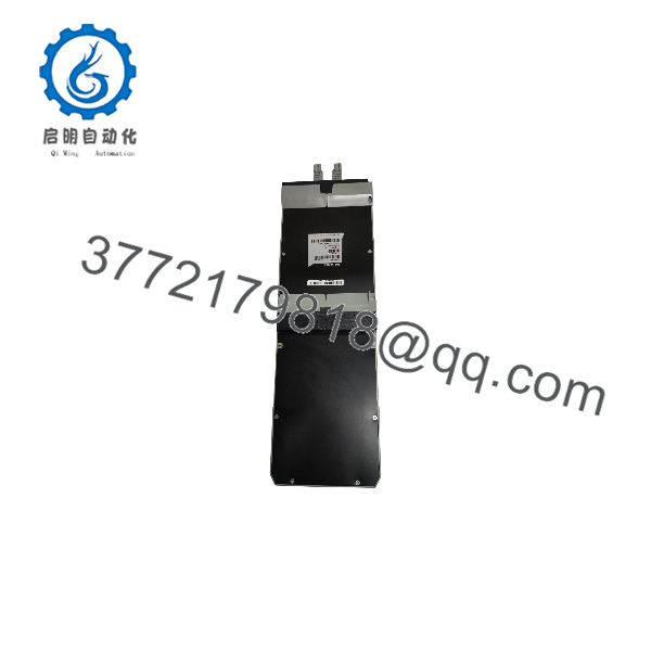
FBM14
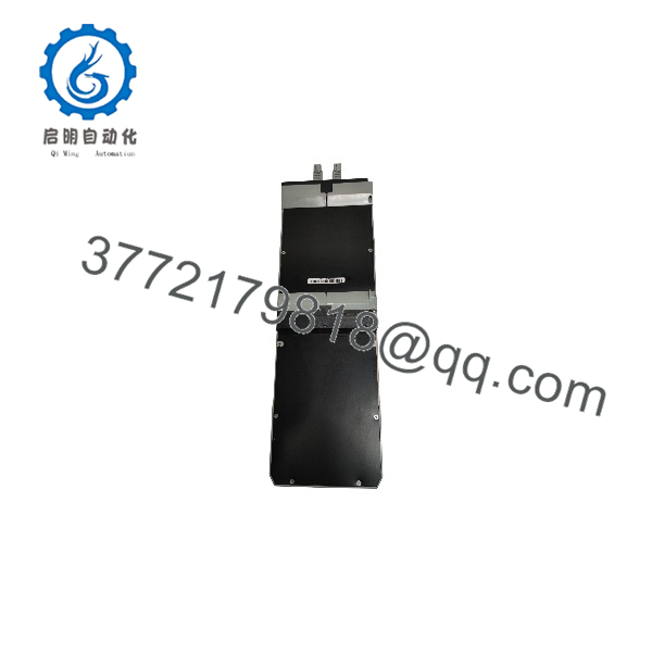
FBM14
Troubleshooting Quick Reference
| Symptom | Possible Cause | Relevance to This Part | Quick Check Method | Recommendation |
|---|---|---|---|---|
| All 8 inputs and 8 outputs are unavailable | main module fault, loss of fieldbus power, poor -to- connection, failed mounting hardware, failed | ✅ High | Check diagnostic and status indications first. Verify the 26–42 V DC fieldbus supply at the I/A Series mounting structure. Inspect the expansion connection after safe isolation. | Do not replace the until the paired and fieldbus power are known good. |
| One input remains OFF despite an active field device | Open field wire, failed limit switch or relay contact, incorrect DC sensing voltage, shared common return fault, failed input channel | ⚠️ Medium | Measure voltage and continuity at the exact terminal-assembly input pair. Compare the actual field state with the DCS point indication. Check the input common shared with related points. | Repair the field device, cable, or terminal issue before replacing the module. |
| One input stays ON after its field contact opens | Welded field contact, shorted cable, moisture in junction box, crossed conductors, failed input channel | ⚠️ Medium | Remove the field signal from the terminal assembly under approved procedure. If the DCS point remains ON with the field conductor isolated, inspect the terminal assembly and module input. | Trace external wiring first. Replace only after the field circuit has been isolated and the point remains incorrect. |
| Several related input points fail together | Shared return open, damaged terminal assembly, broken cable harness, incorrect wiring after maintenance | ⚠️ Medium | Identify whether affected inputs share a common terminal or field cable. Measure the common-return continuity and inspect screw terminals for looseness, corrosion, or overheating. | Repair the shared field circuit before replacing the . |
| Output command is ON in DCS but field device does not energize | Output fuse open, missing external load supply, open field wire, failed relay/solenoid, output load exceeds rating, failed output channel | ⚠️ Medium | Confirm the DCS command and module output state. Measure voltage at the output terminal, then at the field device. Check external output supply and fuses. | Troubleshoot the load circuit first. Replace the module only if its output does not change under a known-good test load. |
| Outputs chatter or drop out during machine operation | 24 V DC field supply sag, loose common, undersized wiring, inductive-noise suppression missing, overloaded output circuit | ⚠️ Medium | Monitor field supply voltage during output operation. Check coil suppression devices, output current, common-return tightness, and cabinet ground bonding. | Correct power and load faults before installing another . A new module will fail again if an inductive load or supply problem remains. |
| DCS reports incorrect point state after replacement | Wrong FBM type, reversed terminal plug, terminal assembly mismatch, DCS database mismatch, field wires landed incorrectly | ✅ High | Compare old and new labels: , P0400YQ, or CM400YQ. Verify the I/A Series configuration, terminal assembly part number, connector keying, and every field wire against drawings. | Do not wire from memory. Restore the original configuration and complete a point-by-point I/O checkout. |
| Module area is hot, discolored, or smells burnt | Loose terminals, overloaded output, wrong field voltage, shorted solenoid, damaged output circuit | ✅ High | Make the area safe. Isolate power, inspect terminals and cable insulation, check output loads for shorts, and inspect suppression diodes or RC snubbers. | Find and correct the overload before replacing the , terminal assembly, or associated hardware. |
Field note: An output often gets blamed when a valve or relay does not move. In many cases, the DCS command is correct and the card is switching, but the field fuse is open, the common is loose, or the solenoid coil has failed. Measure voltage at the output terminal and then at the load before pulling the module.
If you need technical review, provide photos of the label, associated , terminal assembly, affected terminals, LED status, DCS diagnostics, output-voltage readings, and the I/O loop drawing.
Frequently Asked Questions
Is the Foxboro a standalone I/O module?
No. The is a contact/DC I/O expansion module associated with an main module. It adds eight discrete inputs and eight discrete outputs to the I/A Series assembly, while the provides the main fieldbus relationship. A failed , mounting connection, or fieldbus supply can affect the even when the expansion card itself is healthy.
How many I/O points does the provide?
The provides eight contact/DC discrete input channels and eight discrete output channels. It is intended for standard on/off signals and loads, not for analog transmitter or analog valve-positioner service. Confirm the exact termination assembly and output wiring before using it as a replacement.
Is P0400YQ the same as CM400YQ?
Both identifiers appear in supplier listings for Foxboro hardware, but you should use the complete label on the unit being replaced as the purchasing reference. Foxboro legacy assemblies may carry different marketing, assembly, revision, packaging, or terminal-related identifiers. Send a clear photo of the front and side labels before ordering.
Can I replace an with an ?
No. They perform different roles. The is the contact/DC input/output main module, while is the associated expansion module. The cannot replace a failed , and an does not automatically substitute for an installed position. Verify the rack architecture, mounting hardware, and DCS configuration before selecting a replacement.
Can I hot-swap the ?
Do not assume it is hot-swappable. Follow the approved I/A Series maintenance procedure, operating permit, and site safety rules. Removing an can change multiple live discrete signals and outputs. Before removal, identify process impact, place equipment in a safe state, manage alarms under authorization, isolate relevant control or field power where required, and use a grounded ESD wrist strap.
Take a photo before you touch it. A reversed terminal plug or one misplaced common conductor can create a much bigger problem than the original fault.
Why does my output show ON in the DCS but the solenoid is dead?
Check the circuit in this order:
- Confirm the DCS logic actually commands the output
- Check the output terminal for switched voltage
- Check the output fuse and external field power supply
- Measure voltage at the solenoid or relay coil
- Check coil resistance and wiring continuity
- Inspect suppression diode polarity or RC snubber condition
- Confirm the output load does not exceed the approved circuit rating
If voltage leaves the but does not reach the load, the fault is external. If the load receives correct voltage but does not move, check the coil, actuator, or mechanical device. Replace the only after proving that its output channel will not switch with a verified test circuit.
Why are several points failing after a field-power event?
Start with the common cause: field power supply, fuse block, common return, terminal assembly, connector seating, and grounding. The receives fieldbus-related power through its association, while field loads often use separate external power. A single missing common or blown output fuse can make several channels appear failed at once.
Is this New Surplus or Refurbished?
The offered condition must be listed clearly. New Original / New Surplus means unused legacy stock with identity-label and storage-condition checks. Refurbished (tested) means previously used hardware that has been inspected, cleaned, powered, and functionally tested.
For a refurbished Foxboro , ask for actual-unit photos, /P0400YQ label verification, -pair or equivalent bench-communication verification, eight-channel input simulation, eight-channel output switching test with documented load conditions, terminal/connector inspection results, and a written test report. Test videos and photos should be available upon request.
What should I verify before ordering an replacement?
- Exact label: , , and any visible revision marking
- Associated main module model and condition
- I/A Series mounting structure and expansion connection
- Terminal assembly part number and connector orientation
- Number and type of field inputs and output loads
- External field supply voltage, fuse protection, and shared commons
- DCS database configuration for the affected I/O position
- Existing alarm text, module diagnostics, and LED states
- Required condition: New Original/New Surplus or Refurbished (tested)
Keep these checks in mind and you will avoid most replacement rework.



