
 WhatsApp: +86 16626708626
 Email:
  Phone: +86 16626708626
Description
Key Technical Specifications
| Parameter | Value |
|---|---|
| Product Model | FBM201 |
| Manufacturer | Foxboro |
| System Platform | Foxboro I/A Series DCS |
| Product Type | Analog Input Interface Module |
| Input Channels | 8 independent isolated channels |
| Standard Input Signal | 0 to 20 mA DC |
| Compatible Variants | FBM201b: 0 to 100 mV DC; FBM201c: 0 to 5 V DC; FBM201d: 0 to 10 V DC |
| Communication Interface | Redundant 2 Mbps I/A Series Fieldbus |
| Host Interface | FCM or FCP |
| A/D Conversion | Independent Sigma-Delta converter per channel |
| Analog Accuracy | ±0.03 % of span |
| Temperature Coefficient | ±50 ppm/°C |
| Input Channel Isolation | Galvanically isolated channel-to-channel and channel-to-ground |
| Common Mode Rejection | >100 dB at 50/60 Hz |
| Normal Mode Rejection | >95 dB at 50/60 Hz |
| Input Impedance | 61.5 Ω nominal |
| Power Supply | 24 V DC redundant input (+5 % / −10 %) |
| Power Consumption | 7 W maximum |
| Operating Temperature | −20 to +60 °C |
| Storage Temperature | −40 to +85 °C |
| Humidity | 5 to 95 % RH, non-condensing |
| Mounting | I/A Series modular baseplate / Compact FBM baseplate |
| Termination | Dedicated Termination Assembly (TA) |
Specifications are based on Foxboro I/A Series FBM201 documentation. The exact hardware revision and termination assembly should be verified before replacement.
Product Introduction
The Foxboro FBM201 is an 8-channel analog input Fieldbus Module designed for Foxboro I/A Series distributed control systems. It converts 0 to 20 mA DC signals from field transmitters into digital process values for control and monitoring applications. Typical uses include pressure, flow, level, and temperature transmitter integration.
The module provides channel-to-channel isolation, redundant Fieldbus communication, and independent Sigma-Delta signal conversion on each input channel. It is widely used in legacy process plants where I/A Series DCS platforms remain in service.
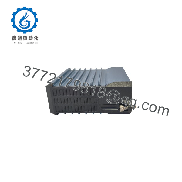
FBM201
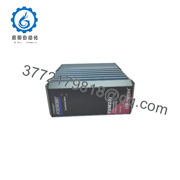
FBM201
Installation & Configuration Guide
Stage 1: Pre-Installation Preparation (Approx. 10 minutes)
⚠️ Safety First
- Notify the control room and maintenance team before removing the FBM201.
- Confirm affected loops are placed into a safe operating state.
- Apply lockout/tagout procedures where required.
- Remove module power and wait at least 5 minutes before handling connections.
Tools Required
- ESD wrist strap
- PH1 screwdriver
- Digital multimeter
- Wire labels
- Smartphone for photos
Data Backup
Before removing the existing module:
- Record the FBM201 model and hardware revision.
- Photograph the module position and termination wiring.
- Record all configured channel assignments.
- Export or document I/O database settings.
- Record transmitter loop details:
- 2-wire or 4-wire transmitter
- Loop power source
- Signal range
Stage 2: Removing the Old Module (Approx. 10 minutes)
Steps
- Open the I/A Series cabinet.
- Confirm the correct FBM201 slot location.
- Label all field wiring before removal.
- Disconnect termination wiring carefully.
- Release the module retaining mechanism.
- Pull the module straight out from the baseplate.
- Inspect connectors for dust, corrosion, or bent pins.
⚠️ Note:
Keep the original until the replacement has passed communication and channel verification. Legacy DCS installations often depend on exact slot addressing and termination hardware.
Stage 3: Installing the New Module (Approx. 10 minutes)
Steps
- Wear an ESD strap before handling the replacement module.
- Verify:
- Model =
- Correct hardware revision
- Correct termination assembly compatibility
- Configuration Clone (Critical):
- Match the original module slot.
- Verify I/O database channel mapping.
- Confirm input range configuration.
- Check transmitter loop wiring.
- Verify Fieldbus communication path.
- Insert the into the mounting baseplate.
- Secure the locking mechanism.
- Reconnect field wiring using the original labels.
Self-Checklist
- Correct installed
- Correct TA verified
- Field wiring secured
- Slot assignment confirmed
- DCS database matches hardware
Stage 4: Power-On & Testing (Approx. 15 minutes)
Pre-Power Check
- Verify 24 V DC module supply.
- Check field loop polarity.
- Confirm no shorts exist between input terminals.
Power-On Steps
- Restore I/O cabinet power.
- Observe FBM status LEDs.
- Verify Fieldbus communication through FCM/FCP.
- Check module health status in the I/A Series workstation.
- Simulate input signals.
- Confirm all eight analog channels read correctly.
⚠️ Troubleshooting Note
- If the module fails communication, check Fieldbus termination and module addressing.
- If input values are incorrect, verify transmitter range and wiring polarity.
- If readings fluctuate, inspect grounding and shielding practices.
Frequently Asked Questions (FAQ)
Q1: Can the Foxboro be hot-swapped under power?
Some Foxboro FBM architectures support online replacement procedures, but this depends on the installed baseplate type, termination assembly, and system configuration. Verify the site maintenance procedure before removing the module. The Compact design allows replacement without removing field termination cabling in supported configurations.
Q2: Is the Foxboro obsolete?
The belongs to the Foxboro I/A Series product family. Many industrial facilities still operate I/A Series systems, so replacement demand continues. Stock availability depends mainly on remaining inventory and surplus channels.
Q3: Are , FBM201b, FBM201c, and FBM201d interchangeable?
No. They share the same product family but accept different input signals.
- 0 to 20 mA DC
- FBM201b: 0 to 100 mV DC
- FBM201c: 0 to 5 V DC
- FBM201d: 0 to 10 V DC
Installing the wrong variant can create incorrect process readings. Always verify the transmitter output range before ordering.
Q4: Will replacing erase the DCS configuration?
No. The control strategy and I/O database remain in the Foxboro control system. However, the replacement module must match the configured slot, signal type, and termination arrangement.
A common field mistake is assuming the module alone defines the signal. In I/A Series systems, the hardware, termination assembly, and database configuration work together.
Q5: Why is surplus pricing lower than OEM pricing?
Legacy automation modules often enter the market through:
- Plant shutdown inventory
- Project excess stock
- Panel builder surplus
- Equipment upgrade programs
Lower pricing does not define the condition. Buyers should confirm whether the unit is:
- New Original / New Surplus: Unused inventory condition.
- Factory Sealed: Original unopened packaging when available.
- Refurbished (tested): Inspected and function-tested before shipment.
Q6: What inspection process should be completed before installing a surplus ?
A professional inspection process should include:
1. Inbound Inspection & Traceability
- Verify source records and packing documentation.
- Confirm model number and revision label.
- Check serial number markings.
- Inspect enclosure condition.
- Verify no corrosion, scratches, repair marks, or contamination.
- Audit accessories.
2. Live Functional Testing
Test environment:
- Genuine Foxboro I/A Series test rack.
Testing steps:
- Power-up LED verification.
- Fieldbus communication test.
- Analog signal simulation.
- Eight-channel input verification.
- Continuous operation monitoring.
- Official test report generation.
3. Electrical Parameter Testing
- Insulation resistance test using 500 V Megger where applicable.
- Ground continuity check.
- Input channel electrical verification.
4. Firmware & Configuration Verification
- Record hardware revision.
- Document module identification data.
- Save configuration records.
- Photograph module labels.
5. Final QC & Packaging
- QC inspector sign-off.
- Anti-static ESD bagging.
- Bubble wrap protection.
- Heavy-duty corrugated packaging.
- QC Passed label with inspection date.
Q7: What are the most common replacement mistakes?
❗ The most common mistake is matching only the model number and ignoring the transmitter signal type.
I have seen maintenance teams replace an with the correct-looking module but discover later that the field transmitter wiring was configured for a different input range.
Common issues include:
- Confusing with voltage input variants.
- Incorrect termination assembly selection.
- Missing loop power requirements.
- Incorrect I/O database mapping.
- Poor shielding or grounding practices.
Document the original wiring, verify the transmitter output range, and confirm the DCS configuration before installation. Those checks prevent most replacement delays.



