
 WhatsApp: +86 16626708626
 Email:
  Phone: +86 16626708626
Description
Key Technical Specifications
| Parameter | Value |
|---|---|
| Manufacturer | Foxboro, formerly Invensys Process Systems; now part of Schneider Electric |
| Module designation | FBM203 |
| Common module part number | P0914SV |
| Product family | Foxboro I/A Series / EcoStruxure Foxboro DCS |
| Product type | Platinum, nickel, or copper RTD input module |
| Input channels | 8 independent RTD input channels |
| Channel isolation | Each channel galvanically isolated from other channels and ground |
| Standard sensor wiring | 2-wire or 3-wire RTD input |
| FBM203 input range | 0–320 Ω per channel |
| Resolution reference | 320 Ω = 64,000 counts |
| Minimum overrange | 327.675 Ω at 65,535 counts |
| Sensor excitation current | 0.19 mA DC nominal |
| Maximum lead resistance | 50 Ω per lead |
| A/D conversion | Independent sigma-delta A/D conversion per channel |
| Integration period | Software configurable |
| Accuracy temperature coefficient | ±50 ppm/°C |
| Redundant input supply | 24 V DC, +5% / −10% |
| Maximum power consumption | 3 W |
| Maximum heat dissipation | 3 W |
| Compatible RTD metals | Platinum, nickel, and copper; sensor curve selection depends on control-system configuration |
| Replacement requirement | Match FBM203/P0914SV identity, sensor wiring, configured RTD curve, terminal assembly, and DCS database definition |
The standard Foxboro FBM203 accepts eight 2-wire or 3-wire RTD inputs across a 0–320 Ω range. Each channel is independent and galvanically isolated, using its own sigma-delta A/D conversion. The FBM203 operates from redundant 24 V DC input power and consumes up to 3 W.
Product Introduction
The Foxboro FBM203, commonly supplied as P0914SV, is an eight-channel isolated RTD input module for Foxboro I/A Series and EcoStruxure Foxboro DCS installations. It reads platinum, nickel, or copper resistance temperature detectors used for process temperature measurement in reactors, exchangers, furnaces, tanks, compressor systems, and utility equipment.
The standard supports 2-wire and 3-wire RTD circuits from 0 to 320 Ω. It is selected where independent channel isolation and reliable temperature signal acquisition matter. Confirm the installed RTD element type, wiring method, range configuration, terminal assembly, and DCS database point definition before ordering.
Troubleshooting Quick Reference
| Symptom | Possible Cause | Relevance to This Part | Quick Check Method | Recommendation |
|---|---|---|---|---|
| All eight RTD points are bad or module is absent | Loss of redundant 24 V DC supply, baseplate or fieldbus fault, module not seated, failed | ✅ High | Check redundant 24 V DC supply at the mounting structure. Verify module status in the DCS and inspect module seating, connector engagement, and baseplate contacts under approved isolation. | Correct supply and baseplate faults before replacing the module. A common failure across all channels rarely starts with eight failed RTDs. |
| One temperature reads open circuit or extreme low/high | Broken RTD lead, loose terminal, damaged sensor element, incorrect 2-wire/3-wire termination, failed channel | ⚠️ Medium | Isolate the loop safely. Measure RTD resistance at the terminal assembly and compare it with the actual process temperature. Check all sensor leads for continuity. | Repair sensor or wiring faults first. Replace the only if a verified resistance value reaches the input terminals but the DCS value remains incorrect. |
| Temperature reading is consistently high or low | Wrong RTD curve, wrong sensor type, lead resistance, poor 3-wire compensation, incorrect engineering range | ⚠️ Medium | Identify the installed sensor: Pt100, Pt1000, Ni, Cu, or another approved curve. Measure resistance at the sensor and at the marshalling terminals. Compare lead resistance between conductors. | Verify the DCS point configuration and sensor type before changing hardware. A Pt100 configured as nickel will never read correctly. |
| Value drifts when nearby equipment starts | Electrical noise, poor shield termination, ground loop, moisture in junction box, damaged cable insulation | ⚠️ Medium | Trend the RTD reading while the suspected equipment starts. Check shield grounding according to the site standard, inspect junction boxes, and test insulation where permitted. | Correct noise, moisture, or grounding faults before replacing the . Each input is isolated, but field wiring can still introduce unstable readings. |
| Two related RTDs show similar error | Shared junction box fault, common cable damage, incorrect field termination, local temperature effect | ❌ Low to Medium | Inspect the shared junction box and cable route. Compare resistance readings at the field and cabinet ends. Verify both channels are configured for the correct RTD type. | Diagnose the shared field installation first. Two simultaneous RTD element failures are less common than a shared wiring issue. |
| Reading jumps after module replacement | Wrong FBM variant, incorrect terminal assembly, different sensor wiring scheme, database configuration not restored | ✅ High | Compare old and replacement labels: and P0914SV. Verify terminal assembly compatibility, channel mapping, wiring method, and RTD curve in the DCS database. | Do not assume all -family variants are interchangeable. Complete a channel-by-channel loop check after replacement. |
| Module fault occurs after handling | ESD damage, bent connector pin, poor seating, damaged backplane contact | ✅ High | Isolate power per site procedure, use a grounded wrist strap, inspect the connector under good light, and reseat the module evenly. | Replace damaged hardware and correct the connection issue before applying power. |
| Reading is wrong only during maintenance or after a cable repair | Lead wires swapped, three-wire compensation lead landed incorrectly, incorrect shield/common connection | ⚠️ Medium | Compare every terminal against the loop drawing. For a 3-wire RTD, identify the two same-color leads at the sensor and confirm the correct compensation terminals. | Do not wire from memory. Photograph the old termination before removal and perform a resistance check before returning the loop to service. |
Field note: The usual replacement trap is not the module—it is a 3-wire RTD with one compensation lead swapped or open. I have watched technicians chase a 15 °C error for hours only to find one same-color lead landed on the wrong terminal. Measure sensor resistance at the field device and again at the cabinet. If the values differ, the card is not your first suspect.
If you need help verifying a failure, provide module photos, the P0914SV label, terminal assembly part number, sensor type, field and cabinet resistance readings, DCS point diagnostics, and the RTD loop drawing.
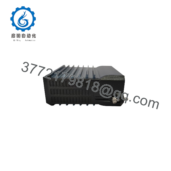
FBM203
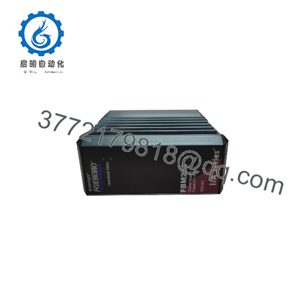
FBM203
Frequently Asked Questions
What does the Foxboro do?
The is an eight-channel RTD temperature input module. It converts resistance values from platinum, nickel, or copper RTD sensors into DCS temperature measurements. Each channel is isolated and independent, allowing multiple temperature circuits to connect without sharing a common measurement path.
Is P0914SV the correct part number for ?
is commonly used for the standard Foxboro module assembly. Confirm the entire label before ordering because the family includes related variants such as FBM203b, FBM203c, and FBM203d, each with different resistance ranges or wiring support. The standard is not automatically interchangeable with every -family variant.
How many RTD inputs does have?
The provides eight RTD input channels. Each channel is independent and galvanically isolated from other channels and ground.
Can I use a 4-wire RTD with a standard ?
No, not as a direct standard connection. The standard supports 2-wire and 3-wire RTD input circuits. The FBM203d variant supports 4-wire RTD sensors within a 0–320 Ω resistance range. Do not try to force a 4-wire sensor onto a standard without checking the approved terminal assembly and I/O documentation; you may lose lead-resistance compensation or create an incorrect measurement.
What resistance range does the standard support?
The standard measures 0–320 Ω per channel. A resistance of 320 Ω equals 64,000 counts, and the minimum documented overrange occurs at 327.675 Ω. The FBM203b, FBM203c, and FBM203d use different ranges or wiring arrangements, so confirm the exact suffix before replacing the module.
Why is my temperature reading wrong after an replacement?
Check the replacement in this order:
- Confirm the replacement is /, not an FBM203b, FBM203c, or FBM203d
- Confirm whether the field sensor is Pt100, Pt1000, nickel, or copper
- Verify 2-wire versus 3-wire termination
- Check the DCS RTD curve and engineering range
- Measure actual sensor resistance at the sensor and terminal assembly
- Check each lead for continuity and resistance balance
- Verify the terminal assembly and channel mapping
A module swap does not correct a wrong RTD curve or crossed compensation lead. Those are the two most common causes of a temperature that is consistently wrong but stable.
Can I hot-swap an ?
Follow the approved Foxboro DCS maintenance procedure and your site’s process-safety rules. Do not assume the module can be removed without operational impact. Pulling an RTD module can place temperature loops into bad-quality status, trigger alarms, freeze control values, transfer control modes, or initiate protective logic depending on the configured strategy.
Before removal, identify the affected loops, place controllers in an approved safe state, notify operations, manage alarms under authorization, verify that no shutdown logic depends on the inputs, and use ESD protection. This is a temperature module, but it can still be tied to a furnace trip, compressor permissive, or reactor control loop.
Is the New Surplus or Refurbished?
The product condition must be stated explicitly in the quotation. New Original / New Surplus means unused legacy inventory with documented identity-label and storage-condition inspection. Refurbished (tested) means a previously used module that has been inspected, powered, and functionally verified.
For a refurbished , request actual-unit photographs, label verification, a 24 V DC power-on test, communication or module-recognition verification, eight-channel resistance simulation across the operating range, channel-isolation check where applicable, and a written test report. Test videos and photos should be available upon request.
What should I verify before ordering an replacement?
- Exact module label: and
- Whether the installed part is standard , FBM203b, FBM203c, or FBM203d
- RTD element type: platinum, nickel, or copper
- Sensor resistance and process temperature range
- Sensor wiring: 2-wire, 3-wire, or 4-wire
- Terminal assembly and cable/connector orientation
- DCS database configuration and RTD curve
- Existing module diagnostics, fault code, and channel behavior
- Required condition: New Original/New Surplus or Refurbished (tested)
Keep these checks in mind and you will avoid most replacement rework.



