
 WhatsApp: +86 16626708626
 Email:
  Phone: +86 16626708626
Description
Key Technical Specifications
| Parameter | Value |
|---|---|
| Manufacturer | Foxboro, formerly Invensys Process Systems; now part of Schneider Electric |
| Module designation | FBM211 |
| Common assembly part number | P0914TN |
| Product family | Foxboro I/A Series / EcoStruxure Foxboro DCS |
| Product type | 0–20 mA analog current input module |
| Input channels | 16 group-isolated, independent channels |
| Supported field signals | 2-wire 4–20 mA transmitters, self-powered 0–20 mA sources, and compatible line-monitored discrete circuits |
| Input range | 0–20.4 mA DC per channel |
| Input current protection | 33 mA current limit per channel |
| Measurement accuracy | ±0.03% of span, including linearity |
| Temperature coefficient | ±50 ppm/°C |
| A/D conversion | Multiplexed sigma-delta converter |
| Integration period | Software configurable |
| Input impedance | 61.9 Ω nominal |
| Common-mode rejection | Greater than 100 dB at 50/60 Hz |
| Normal-mode rejection | Greater than 35 dB at 50/60 Hz |
| Field device cable distance | Depends on transmitter compliance voltage, wire gauge, loop voltage drop, and termination assembly |
| HART compatibility | Meets high-impedance input requirements for HART devices; confirm HART system architecture and termination arrangement |
| Fieldbus supply | Redundant 24 V DC, +5% / −10% |
| Power consumption | 7 W maximum at 24 V DC; 11 W maximum with all channels at 20.4 mA using internal field power |
| Heat dissipation | 3 W maximum |
| Mounting | Foxboro modular baseplate; DIN rail or 19-inch rack mounting arrangement |
| Module weight | Approximately 284 g (10 oz) |
| Replacement requirement | Match FBM211/P0914TN label, terminal assembly, field-power method, I/O database configuration, and HART requirements |
The Foxboro FBM211 contains 16 0–20 mA DC analog input channels, each suitable for a two-wire transmitter or self-powered current source. The documented input range is 0–20.4 mA, with ±0.03% of span accuracy and 61.9 Ω nominal input impedance. The original product specification also states that the channels are isolated from ground and module logic.
Product Introduction
The Foxboro FBM211, commonly marked P0914TN, is a 16-channel analog current-input module for I/A Series and EcoStruxure Foxboro DCS systems. It acquires 4–20 mA process signals from pressure, temperature, flow, level, position, and analytical transmitters, then transfers the scaled values to the redundant Foxboro module fieldbus.
The FBM211 is used where a high-density current-input card is needed with group isolation from ground and module logic. It supports 0–20.4 mA inputs and accepts standard two-wire transmitters or self-powered current sources. Confirm the terminal assembly, loop-power arrangement, channel configuration, and field transmitter type before ordering.
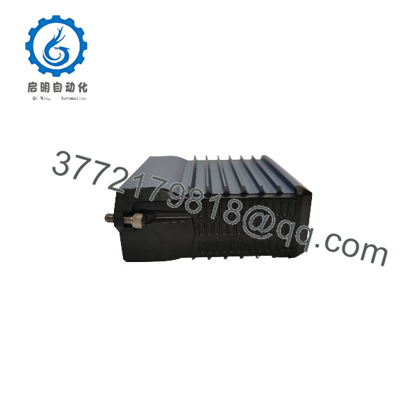
FBM211
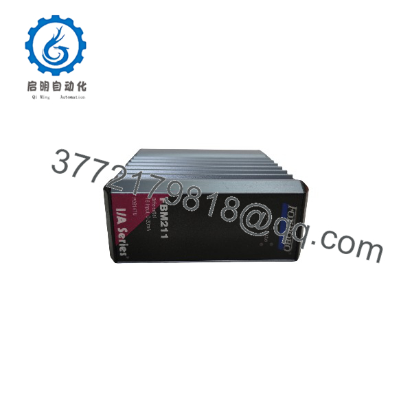
FBM211
Troubleshooting Quick Reference
| Symptom | Possible Cause | Relevance to This Part | Quick Check Method | Recommendation |
|---|---|---|---|---|
| All 16 analog points show bad quality or module is absent | Loss of redundant 24 V DC supply, baseplate or fieldbus fault, poor module seating, failed FBM211 | ✅ High | Check DCS diagnostics first. Measure redundant 24 V DC at the baseplate supply points and inspect module seating, connector engagement, and baseplate contacts under an approved maintenance procedure. | Correct supply, baseplate, or fieldbus faults before replacing the . A failure across all channels is usually not 16 failed transmitters. |
| One transmitter reads 0 mA or below range | Open loop, failed transmitter, missing loop power, open fuse, broken field cable, failed input channel | ⚠️ Medium | Measure loop current in series at the termination assembly. Check transmitter supply voltage and confirm continuity from transmitter to cabinet. Compare the measured current with the DCS value. | Repair the transmitter, loop power, fuse, or cable first. Replace only if valid current reaches the input terminal but the DCS value remains incorrect. |
| One point is fixed near 20 mA | Failed transmitter, process overrange, shorted wiring, incorrect range configuration, failed channel | ⚠️ Medium | Measure actual loop current at the terminal assembly. If it is near 20 mA, determine whether the transmitter is reporting a real process condition or configured fault current. | Check transmitter diagnostics and process conditions before touching the module. |
| Several channels read low after cabinet maintenance | Common 24 V DC field-power loss, wrong terminal block connection, blown fuse group, disconnected multipair cable | ⚠️ Medium | Identify whether affected loops share a terminal assembly, power source, fuse block, or cable. Measure field power and loop current on more than one affected channel. | Restore shared field power or wiring before replacing the . |
| Reading is noisy or drifts | Ground loop, poor shield termination, moisture in junction box, transmitter instability, electrical noise, damaged cable | ⚠️ Medium | Trend the point and measure loop current with a calibrated meter. Check cable shields and cabinet grounding against site practice. Inspect field junction boxes for moisture or corrosion. | Correct field noise, grounding, and transmitter problems before replacing hardware. |
| DCS reading differs from a handheld meter | Incorrect DCS scaling, transmitter calibration issue, bad loop calibration, measurement at different loop location, input-channel fault | ⚠️ Medium | Place the loop in an approved test state. Inject known values—4, 8, 12, 16, and 20 mA—at the termination assembly and compare raw count, engineering value, and handheld meter reading. | Verify DCS range and transmitter calibration first. Replace the module only if it fails a controlled current-injection test. |
| HART communicator cannot connect | Improper loop impedance, incorrect termination arrangement, transmitter issue, communication wiring issue, incompatible system configuration | ❌ Low to Medium | Check loop current and wiring. Confirm the input channel and termination arrangement meet the HART high-impedance requirement. Test the transmitter locally if permitted. | Investigate the HART loop architecture before replacing the . HART communication failure does not automatically mean analog measurement failure. |
| Module faults after replacement | Wrong part, wrong terminal assembly, configuration not restored, ESD damage, bent connector pin, incorrect field-power wiring | ✅ High | Compare old and new labels: and P0914TN. Verify termination assembly part number, DCS database assignment, input ranges, field-power scheme, and all terminal wiring. | Use ESD controls and perform a point-by-point loop check after replacement. Do not wire from memory. |
Field note: A 4–20 mA input card is often blamed because the DCS number is wrong. In the field, the usual causes are a transmitter in fault mode, a missing 24 V DC loop supply, a corroded terminal, or a range mismatch. Before pulling the , inject a known current directly at the termination assembly. That one test separates card faults from almost everything else.
If you need technical support, provide a photo of the /P0914TN label, terminal assembly number, module diagnostic state, DCS point configuration, measured loop current, transmitter supply voltage, and the relevant loop diagram.
Frequently Asked Questions
What does the Foxboro do?
The is a 16-channel analog input module for 0–20 mA and 4–20 mA process loops. It reads current signals from two-wire transmitters or self-powered current sources and sends the digitized values to the Foxboro I/A Series or EcoStruxure Foxboro DCS.
Is P0914TN the same as ?
is a common assembly part number associated with the Foxboro . Confirm the complete front and side label, revision markings, and terminal assembly before ordering. Legacy Foxboro equipment may carry module, assembly, terminal, and packaging identifiers that are related but not interchangeable.
How many analog inputs does provide?
The provides 16 independent analog current-input channels. The channels are group-isolated from ground and module logic, but they are not necessarily individually galvanically isolated from one another. Do not assume each channel has its own isolated field supply; verify the installed termination assembly and field-power design.
Can I connect a 4–20 mA transmitter to the ?
Yes. The is designed for standard two-wire 4–20 mA transmitters, as well as self-powered 0–20 mA sources. The supported input range is 0–20.4 mA DC per channel. Confirm whether the loop uses external field power or a compatible termination assembly that supplies internal power before wiring the transmitter.
Can I connect voltage signals directly to ?
No. The measures current, not direct voltage. Do not land a 0–10 V, 1–5 V, thermocouple, RTD, or millivolt signal directly on this card. Use the appropriate Foxboro analog input module or approved signal conditioner for the actual field-signal type. A wrong signal type can produce bad data or damage the input circuit.
Does support HART transmitters?
The channels meet the high-impedance requirements for HART devices. However, successful HART communication also depends on transmitter compatibility, loop wiring, termination assembly, loop resistance, field power, and the DCS HART management architecture. Do not promise HART access solely because the analog value reads correctly.
Can I hot-swap an ?
Follow the approved Foxboro DCS maintenance procedure and site operating rules. Do not assume a card swap is harmless. Removing can place up to 16 analog signals into bad quality, hold or drive control strategies to their configured fallback state, generate alarms, or affect shutdown permissives.
Before removal, identify affected loops, notify operations, put controllers into an approved mode, confirm no protective logic depends on the card, document terminal wiring, and use a grounded ESD wrist strap. In a running plant, that planning matters more than the physical swap.
Why is my 4–20 mA reading wrong?
Check the loop in this order:
- Measure actual current at the terminal assembly
- Check transmitter supply voltage
- Confirm transmitter calibration and configured range
- Verify DCS engineering range and scaling
- Check terminal tightness, cable continuity, and loop fuses
- Inspect shield grounding and junction boxes
- Inject known 4, 8, 12, 16, and 20 mA values at the cabinet
If the reads the injected values correctly, the module is not your root cause. Focus on the transmitter, wiring, or DCS configuration.
Is this New Surplus or Refurbished?
The seller should state condition explicitly. New Original / New Surplus means unused legacy inventory with verified identity labels, connector condition, and storage history. Refurbished (tested) means a used module that has been inspected, cleaned, powered, and functionally checked.
For a refurbished , request actual-unit photos, label evidence, 24 V DC power-on verification, DCS or bench communication test, 16-channel current-injection results, representative 4–20 mA accuracy checks, connector inspection, and a written test report. Test videos and photos should be available upon request.
What should I verify before ordering an replacement?
- Exact module label: and
- Installed baseplate and module location
- Termination assembly part number and connector orientation
- Field devices connected to each affected channel
- External versus internal loop-power arrangement
- DCS channel configuration, scaling, and alarm limits
- HART requirements and current loop architecture
- Existing module diagnostics and fault history
- Required condition: New Original/New Surplus or Refurbished (tested)
Keep these checks in mind and you will avoid most replacement rework.



