
 WhatsApp: +86 16626708626
 Email:
  Phone: +86 16626708626
Description
Key Technical Specifications
| Parameter | Value |
|---|---|
| Model | FBM216 |
| Manufacturer | Foxboro (Schneider Electric) |
| Product Type | HART Communication Redundant Input Interface Module |
| Input Channels | 8 group-isolated analog input channels |
| Input Signal | 4–20 mA with HART FSK communication |
| Redundancy | FBM-level redundant module pair |
| HART Versions | Version 5, 6, and 7 compatible |
| Communication Speed | 2 HART messages/second/device |
| Resolution | 15-bit Sigma-Delta A/D conversion |
| Analog Accuracy | ±0.075% of full scale |
| Update Rate | 100 ms |
| Maximum Field Device Distance | Up to 3,030 m (10,000 ft) |
| Loop Supply | 24 VDC internal loop supply (model dependent) |
| Mounting | Modular baseplate with DIN rail or rack installation |
The FBM216 supports eight analog input channels that accept standard 4–20 mA signals or HART-enabled field devices. Two modules can be configured as a redundant Master/Tracker pair to maintain process availability during module replacement or hardware faults.
Product Introduction
The Foxboro FBM216 is a redundant HART communication input interface module developed for the Foxboro I/A Series distributed control system. It combines conventional analog input acquisition with HART digital communication, allowing process measurements and intelligent device diagnostics over the same two-wire loop.
Unlike a standard analog input module, the FBM216 operates as a redundant pair. One module functions as the Master while the second tracks all input activity. If one module fails or is replaced, the companion module continues servicing field devices, minimizing interruption to critical process operations.

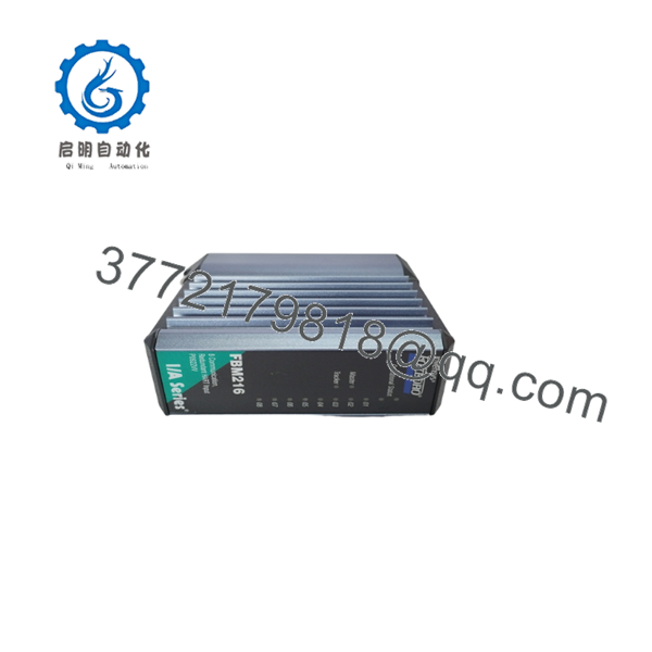
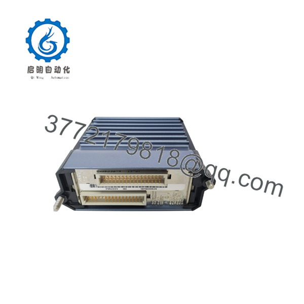
- FBM216
- FBM216
Installation & Configuration Guide
Stage 1 – Pre-Installation Preparation (10 Minutes)
⚠️ Safety First
- Notify operations before shutdown.
- Perform Lock-Out/Tag-Out (LOTO).
- Remove cabinet power.
- Wait at least five minutes before handling the module.
Required Tools
- ESD wrist strap
- Phillips screwdriver
- Digital multimeter
- Wire identification labels
- Smartphone for recording wiring
Before Removal
- Back up the Foxboro configuration database.
- Record installed module revision.
- Photograph all field wiring and termination assemblies.
- Document HART device addresses if asset management is used.
Stage 2 – Removing the Existing Module (5 Minutes)
- Label every field cable.
- Disconnect the termination assembly carefully.
- Release the module latch.
- Remove the without twisting the connectors.
⚠️ Retain the original module until all loop tests are complete.
Inspect:
- Baseplate connectors
- Module contacts
- Dust accumulation
- Moisture
- Corrosion
Stage 3 – Installing the New (10 Minutes)
- Wear an ESD wrist strap.
- Verify the exact part number and hardware revision.
- Install the module completely into the baseplate.
- Reconnect the termination assembly.
- Confirm all wiring matches the recorded documentation.
Checklist:
- ✔ Module fully seated
- ✔ Wiring verified
- ✔ Grounding confirmed
- ✔ Redundant partner recognized
Stage 4 – Power-Up & Commissioning (10 Minutes)
- Verify the 24 VDC supply.
- Restore cabinet power.
- Check module status LEDs.
- Verify communication with the Foxboro controller.
- Confirm HART device detection.
- Compare live analog values with field instruments.
- Verify redundancy status (Master/Tracker).
⚠️ Common Issues
No HART communication
- Check loop resistance.
- Verify HART transmitter compatibility.
- Confirm termination assembly wiring.
Redundancy fault
- Verify both modules are the same revision.
- Confirm redundant configuration in the engineering database.
Incorrect analog value
- Check transmitter calibration.
- Verify loop polarity.
- Inspect field wiring for excessive resistance.
Frequently Asked Questions (FAQ)
Q1. What is the primary advantage of the over a standard analog input module?
The combines analog measurement with HART digital communication and supports redundant operation. It allows engineers to monitor process variables while accessing transmitter diagnostics and configuration without additional wiring.
Q2. How many channels does the support?
The module provides eight analog input channels, each accepting either a conventional 4–20 mA signal or a HART-enabled device.
Q3. Can the be replaced without shutting down the process?
In a redundant installation, one module can typically be replaced while the companion module maintains field input processing. However, follow your plant’s maintenance procedures and verify the system architecture before performing online replacement.
Q4. Which HART protocol versions are supported?
The supports field instruments compliant with HART Version 5, Version 6, and Version 7 specifications.
Q5. What should I verify before ordering a replacement module?
Verify:
- Exact part number (such as P0917TN or P0922VV)
- Hardware revision
- Termination assembly compatibility
- Foxboro DCS software version
- Redundancy configuration
Matching these items reduces commissioning time and avoids unexpected communication issues.
Q6. Is the still used in modern plants?
Yes. Although it is considered a legacy Foxboro I/A Series product, many power generation, refining, chemical, and pharmaceutical facilities continue to operate modules because of their reliability and compatibility with installed HART instrumentation. New surplus inventory and professionally tested spare units remain common options for maintenance programs.



