
 WhatsApp: +86 16626708626
 Email:
  Phone: +86 16626708626
Description
Key Technical Specifications
| Parameter | Value |
|---|---|
| Manufacturer | Foxboro, formerly Invensys Process Systems; now part of Schneider Electric |
| Module designation | FBM217 |
| Common assembly part number | P0914TR |
| Product family | Foxboro I/A Series / EcoStruxure Foxboro DCS |
| Product type | Discrete input interface module |
| Input channel count | 32 group-isolated DC voltage input channels |
| Standard field-signal range | 15–60 V DC |
| Higher-voltage signal support | 120 V AC / 125 V DC and 240 V AC through the correct Foxboro termination assembly |
| ON-state voltage | 15–30 V DC |
| OFF-state voltage | 0–5 V DC |
| Input current | 2.2 mA typical at 30 V DC input |
| ON-state source resistance | 1 kΩ maximum at 15 V DC |
| OFF-state source resistance | 100 kΩ minimum at 30 V DC |
| Input filter/debounce | Configurable: no filtering, 4 ms, 8 ms, 16 ms, or 32 ms |
| Pulse-count capability | Up to 250 Hz maximum |
| Isolation | 32 group-isolated channels; select termination assemblies provide channel isolation for applicable input circuits |
| Communications | Redundant module fieldbus to associated FCM or FCP |
| Redundant supply input | 24 V DC, +5% / −10% |
| Maximum power consumption | 3 W at 24 V DC |
| Maximum heat dissipation | 5 W at 24 V DC |
| Operating temperature | −20 to +70 °C (−4 to +158 °F) |
| Relative humidity | 5–95%, noncondensing |
| Environmental rating | ISA S71.04 Class G3 harsh industrial environment |
| Mounting | Modular baseplate; DIN rail or 19-inch rack arrangement |
| Approximate module weight | 454 g (1.0 lb) |
| Replacement requirement | Match FBM217/P0914TR, terminal assembly, input-voltage class, field wiring, DCS configuration, and redundancy architecture |
The Foxboro FBM217 provides 32 discrete DC voltage inputs. Its documented standard input service is 15–60 V DC, while the correct termination assembly extends the system to 120 V AC/125 V DC or 240 V AC circuits. It also supports configurable filtering from no filtering to 32 ms and pulse counting up to 250 Hz.
Product Introduction
The Foxboro FBM217, commonly identified by part number P0914TR, is a 32-point discrete input module for Foxboro I/A Series and EcoStruxure Foxboro DCS systems. It acquires equipment-status, relay-contact, valve-limit, motor-starter, breaker-auxiliary, alarm, and permissive signals and transfers those states to the control system.
The FBM217 is intended for voltage-based discrete inputs, not as a universal dry-contact card. Its termination assembly determines whether the field circuit operates at standard low-voltage DC, 120 V AC/125 V DC, or 240 V AC. Verify the module, termination assembly, field voltage, and DCS database as one matched set before ordering.
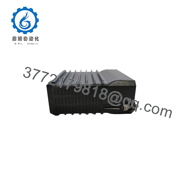
FBM217
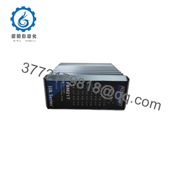
FBM217
Troubleshooting Quick Reference
| Symptom | Possible Cause | Relevance to This Part | Quick Check Method | Recommendation |
|---|---|---|---|---|
| All 32 input points show bad quality or module is absent | Loss of redundant 24 V DC supply, module fieldbus fault, baseplate issue, poor module seating, failed FBM217 | ✅ High | Check the DCS diagnostic page first. Measure 24 V DC at the modular baseplate supply, inspect module seating and connectors, and verify communication to the associated FCM or FCP. | Restore supply, fieldbus, or baseplate integrity before replacing the . A complete 32-point failure is usually a common infrastructure issue. |
| One point remains OFF with its field device energized | Open field wire, blown fuse, failed relay/limit switch, insufficient input voltage, wrong termination assembly, failed input channel | ⚠️ Medium | Measure voltage at the exact termination-assembly input terminal. For standard service, verify an ON-state voltage within 15–30 V DC. Check the field device and its common path. | Repair the field circuit first. Replace the module only if the correct voltage reaches the termination assembly and the DCS point remains OFF. |
| One point remains ON after its field contact opens | Welded field relay, shorted cable, water ingress, crossed conductors, failed termination assembly, failed channel | ⚠️ Medium | Disconnect the field conductor at the termination assembly under approved procedure. If the DCS point remains ON, inspect the termination assembly and module channel. If it changes OFF, troubleshoot the external circuit. | Isolate the field circuit before condemning the . |
| Several related points fail together | Shared field power lost, common return fault, terminal assembly connector loose, multipair cable fault, cabinet power event | ⚠️ Medium | Check fuse groups, field power, common terminals, cable connectors, and adjacent points that share the same field source. Inspect the termination assembly for loose or heat-damaged terminals. | Correct the shared field issue before replacing the input module. |
| Input status flickers or chatters | Contact bounce, electrical noise, damaged cable shield, weak field voltage, filter time set too low | ⚠️ Medium | Trend the point at high resolution, inspect the actual field contact, and measure input voltage during switching. Review the configured filter setting: none, 4, 8, 16, or 32 ms. | Correct the field problem first. Increase debounce only when the additional delay does not conflict with the process or safety response requirement. |
| Pulse count is inaccurate or missing | Pulse frequency above 250 Hz, noisy source, incorrect input configuration, bad field wiring | ⚠️ Medium | Measure pulse frequency using a calibrated frequency counter or oscilloscope. Confirm the signal is within the documented 0–250 Hz range and verify wiring at the termination assembly. | Use a suitable high-speed input interface when the source exceeds 250 Hz. Do not try to solve a frequency-limit problem with filtering. |
| Input states change after an replacement | Incorrect P0914TR module, wrong terminal assembly, field terminals transferred incorrectly, configuration mismatch, wrong voltage class | ✅ High | Compare old and new front/side labels, termination assembly identification, DCS database card type, and terminal orientation. Perform point-by-point verification with the loop drawings. | Do not wire from memory. Validate all 32 points before returning the unit to automatic service. |
| Replacement module fails after energizing | Wrong voltage landed on low-voltage TA, surge event, poor cabinet grounding, wiring short, ESD damage | ✅ High | Verify actual field voltage and TA rating before applying power. Inspect suppression, surge protection, ground bonding, and terminal condition. | Eliminate the electrical cause before installing another . A new input card will not survive a wiring mismatch or unresolved surge path. |
Field note: The most expensive replacement mistake is selecting the correct module but leaving the wrong termination assembly in place. The card may fit and communicate while the field voltage is incompatible with the terminal interface. Check the termination assembly part number before you buy anything.
If you need support, send photos of the /P0914TR label, terminal assembly, baseplate, affected wiring, DCS diagnostics, measured field voltage, and the I/O loop drawing.
Frequently Asked Questions
What does the Foxboro do?
The is a 32-channel discrete input module for reading on/off field signals in Foxboro I/A Series and EcoStruxure Foxboro DCS systems. Typical applications include motor feedback, valve position limits, relay contacts, breaker status, alarm contacts, local/remote selectors, and process permissives.
Is P0914TR the correct part number for ?
is the common assembly number associated with the module. Confirm the full module label, visible revision, baseplate arrangement, and termination assembly before ordering. A product listing that states only “” does not confirm that the offered part matches your installed field interface.
Does accept 120 V AC, 125 V DC, or 240 V AC signals?
It can support those signals only through the correct Foxboro termination assembly. The itself provides 32 discrete input channels, while associated termination assemblies provide the voltage attenuation, optical isolation, and field interface required for 120 V AC/125 V DC or 240 V AC circuits. Do not land those voltages without confirming the exact terminal assembly and drawing.
Can I use for dry contacts?
Not by connecting a dry contact directly without considering the field interface. The standard accepts a two-wire input from a DC voltage source. A dry-contact application needs an appropriate external excitation or approved termination-assembly arrangement. Confirm the field wiring drawing and site design before using it for contact status.
What filter time should I use?
The supports no filtering, 4 ms, 8 ms, 16 ms, or 32 ms debounce/filter settings. Use the minimum value that rejects contact bounce and electrical noise while still meeting the required process response time.
For example, a noncritical mechanical limit switch may tolerate 16 or 32 ms. A fast equipment interlock may require 4 ms or no filtering, but only after confirming it will not nuisance-trip from noise. Do not change a filter setting on safety-related or trip-related logic without an approved change procedure.
Can count pulses?
Yes, within limits. The documented maximum pulse count rate is 250 Hz. That works for low-speed pulse and event applications, but it is not suitable for encoder feedback or high-frequency flowmeter pulses. Measure the actual maximum source frequency before assigning the signal to this module.
Can I hot-swap an ?
Follow the approved Foxboro DCS maintenance procedure and your site operating rules. Do not assume removing an input module is harmless. Pulling the card can drive 32 status signals to bad quality, cause alarm floods, block equipment starts, or affect permissive and trip logic.
Before removal, identify every affected input in the control strategy, notify operations, place affected equipment in a safe state, handle bypasses only under formal authorization, confirm the replacement identity, and wear a grounded ESD wrist strap.
Why does a field input show ON when the contact is open?
Start at the terminal assembly. Measure the real input voltage, inspect the field contact, check cable insulation, verify the common return, and temporarily isolate the field conductor under approved procedure. If the DCS input drops when the conductor is removed, the problem is outside the . If it remains ON after the field wiring is isolated and the termination assembly is confirmed correct, then the termination assembly or module channel becomes a valid suspect.
Is this New Surplus or Refurbished?
The condition must be explicit. New Original / New Surplus means unused legacy inventory with documented label, connector, and storage-condition inspection. Refurbished (tested) means a previously installed module that has been inspected and functionally tested.
For a refurbished , request actual-unit photos, label confirmation, 24 V DC power-on verification, fieldbus communication test, 32-channel discrete-input simulation, filter-function verification, pulse-input verification where applicable, terminal-connector inspection, and a written test report. Test videos and photos should be available upon request.
What should I verify before ordering an replacement?
- Exact module label: , , and revision marking
- I/A Series baseplate and FCM/FCP fieldbus architecture
- Termination assembly part number and connector orientation
- Field-signal class: low-voltage DC, 120 V AC, 125 V DC, or 240 V AC
- External field power, fuse protection, and common-return design
- Any pulse frequency, ensuring it remains at or below 250 Hz
- Input filter configuration and process response-time requirements
- DCS database card type, alarm configuration, and diagnostic history
- Required condition: New Original/New Surplus or Refurbished (tested)
Keep these checks in mind and you will avoid most replacement rework.



