
 WhatsApp: +86 16626708626
 Email:
  Phone: +86 16626708626
Description
Key Technical Specifications
| Parameter | Value |
|---|---|
| Manufacturer | Foxboro, formerly Invensys Process Systems; now part of Schneider Electric |
| Part number | P0916QD |
| Associated hardware | FBM218 and FBM237 |
| Common product designation | FBM218/237 Redundant Adapter |
| Product family | Foxboro I/A Series DCS |
| Product type | Redundant adapter / redundancy interface accessory |
| Primary function | Provides the hardware interface required for redundant FBM218 or FBM237 module arrangements |
| System use | Maintains dual-path module architecture for supported I/A Series analog I/O applications |
| Active I/O channels | None; this is not an analog input, analog output, or discrete I/O module |
| Field signal processing | None; it does not measure, scale, or generate field signals |
| Fieldbus communication | No independent DCS fieldbus node function |
| Firmware | None; passive or interface-level redundancy hardware |
| Configuration requirement | Redundant module pairing, compatible baseplate/mounting hardware, correct terminal assembly, and approved DCS I/O configuration |
| Compatible module class | Only use with the intended FBM218 or FBM237 arrangement; do not assume compatibility with FBM203, FBM211, FBM217, FBM219, FBM232, or FBM242 |
| Failure mode | A faulty adapter or connector can cause module-pair mismatch, loss of redundancy, intermittent field channels, or total I/O bad quality |
| Installation requirement | Remove module/baseplate power as required by the approved Foxboro maintenance procedure; use ESD protection |
| Replacement requirement | Match P0916QD exactly and confirm the installed FBM218/FBM237 redundant architecture before purchase |
P0916QD is consistently identified as a Foxboro FBM218/237 Redundant Adapter. It is accessory hardware for redundant I/O architecture, not an eight-channel 0–20 mA analog input module, an eight-slot baseplate, a seal label, or a standalone fieldbus module. Several online listings assign conflicting functions to P0916QD, so the physical label and installed hardware arrangement must control the replacement decision.
Product Introduction
The Foxboro P0916QD is a redundancy adapter used with and FBM237 hardware in legacy Foxboro I/A Series DCS installations. It forms part of the physical connection arrangement that allows a supported redundant I/O pair to maintain operation when one module path is unavailable.
This part does not read analog signals, power field transmitters, switch outputs, or communicate independently with the DCS. It is a model-specific interface accessory. Before ordering, confirm that the installed part is actually marked P0916QD and that the cabinet contains the associated or FBM237 redundant module arrangement.
Troubleshooting Quick Reference
| Symptom | Possible Cause | Relevance to This Part | Quick Check Method | Recommendation |
|---|---|---|---|---|
| DCS reports redundant I/O pair mismatch or redundancy unavailable | Failed or missing adapter, one /237 module offline, connector not seated, incompatible paired modules, configuration issue | ✅ High | Check DCS diagnostics for the exact module-pair alarm. Verify both /237 modules are present, powered, healthy, and recognized. Isolate power as required and inspect seating and connector condition. | Confirm the paired modules and configuration first. Replace only after a known-good module pair still reports a physical redundancy-path fault. |
| Primary module operates but backup module is not recognized | Backup FBM failed, adapter connector damage, module revision mismatch, incorrect slot, backplane/baseplate fault | ⚠️ Medium | Swap modules only under the approved procedure, then observe whether the fault follows a module or remains with the adapter location. Inspect connector pins and mounting alignment under good light. | If the fault follows the module, replace the module. If both known-good modules fail only through one adapter position, replace or inspect the mounting hardware. |
| Both redundant modules report bad quality | Loss of redundant 24 V DC supply, fieldbus/baseplate problem, termination assembly fault, adapter issue, field circuit failure | ⚠️ Medium | Check both 24 V DC feeds, baseplate status, fieldbus diagnostics, terminal assembly condition, and field wiring. Do not assume the adapter is the cause because both modules are affected. | Diagnose power and common mounting hardware first. A does not create or regulate module supply power. |
| Channels become intermittent after maintenance | Adapter not fully seated, bent or contaminated connector pins, loose module latches, connector strain, ESD damage | ✅ High | Isolate the affected assembly safely. Remove and inspect the adapter and both modules for bent pins, oxidation, debris, cracked housing, or misalignment. Reseat evenly without forcing connectors. | Replace damaged adapter hardware. Never force a module or adapter into an incorrectly keyed location. |
| Analog values disagree between redundant paths | FBM configuration mismatch, different calibration/variant, terminal assembly problem, field signal issue, module fault | ❌ Low to Medium | Check module identities, DCS configuration, diagnostics, field current/voltage, and terminal assembly wiring. Compare readings using an approved loop simulator. | Troubleshoot the active I/O modules and field loop before replacing . The adapter does not perform analog conversion or scaling. |
| Redundancy fault appears after a module replacement | Wrong module family, incorrect revision, module inserted in wrong location, adapter omitted, DCS configuration not restored | ✅ High | Compare every label: or , , baseplate position, termination assembly, and configured I/O type. Review the before-and-after hardware layout photo. | Restore the original architecture. Do not mix module families based on connector fit alone. |
| Adapter area shows heat, discoloration, or physical damage | Connector stress, incorrect insertion, prior electrical event, contaminated cabinet, damaged mounting hardware | ✅ High | De-energize according to plant procedure. Photograph the condition, inspect connectors, verify no pin damage, and inspect nearby baseplate/module contacts. | Replace visibly damaged hardware and investigate the root cause before energizing a new adapter. |
| New does not restore redundancy | Incorrect product, hidden baseplate damage, failed paired module, wrong DCS configuration, termination assembly problem | ⚠️ Medium | Verify the replacement label is . Test with known-good compatible /237 modules where permitted. Check DCS diagnostics and physical architecture against the original drawing. | Escalate with photos and diagnostic logs. Do not replace multiple parts blindly. |
Field note: The mistake I see most often is calling an I/O module and replacing it because one analog point looks wrong. It is an adapter. If the analog value is wrong but the redundant pair is healthy, start with the transmitter, termination assembly, field wiring, and actual / module—not the adapter.
If you need technical support, send photos of the label, both paired module labels, baseplate position, termination assembly, connector condition, DCS redundancy diagnostics, and the relevant I/O architecture drawing.
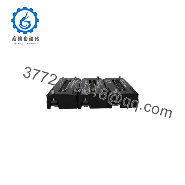
FBM218237 P0916QD
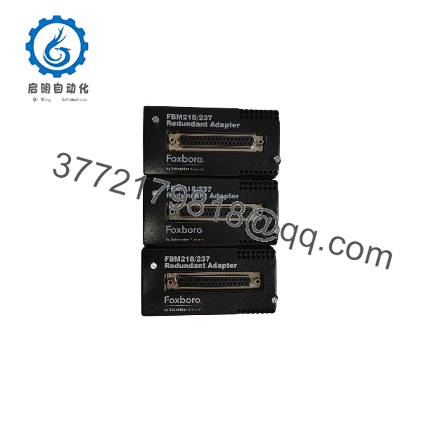
FBM218237 P0916QD
Frequently Asked Questions
What is Foxboro ?
is the redundant adapter used with Foxboro and I/A Series hardware. It is part of the physical redundancy arrangement that supports paired modules. It is not a standalone analog I/O module or a general-purpose baseplate.
Is an analog input module?
No. Some reseller pages incorrectly describe as an analog input interface, an eight-slot baseplate, or an input-channel power module. Those descriptions conflict with multiple sources identifying it as the /237 Redundant Adapter. Use the physical product label and the installed Foxboro architecture to determine what you need.
What modules does work with?
is intended for Foxboro and redundancy arrangements. Do not substitute it for adapters used with other FBM families. The connector may look similar, but the physical architecture, termination scheme, and redundancy logic may differ.
Does require firmware or programming?
No. The is interface hardware and does not have standalone firmware, IP settings, fieldbus addressing, or a downloadable control program. The relevant configuration exists in the paired / modules and the Foxboro DCS database.
Before replacement, document the system configuration anyway. The adapter replacement may require removal and reseating of the modules, which can expose an unrelated module, baseplate, or connector fault.
Can I hot-swap ?
Do not assume it can be hot-swapped. It is part of a redundancy connection path, so removing it can compromise the backup path or interrupt the paired I/O assembly. Follow the approved Foxboro maintenance procedure, identify the process loops affected, place those loops in a safe approved state, notify operations, and use lockout/tagout where required.
Take clear photos of the adapter, paired modules, and terminal assembly before removal. It is the most reliable way to prevent a reversed or incomplete reinstallation.
Why does the DCS show “redundancy unavailable” after I replaced a module?
Check these items in order:
- Confirm both paired modules are the correct or type.
- Verify that both modules are fully seated and latched.
- Confirm the adapter is present, fully seated, and undamaged.
- Inspect connector pins and baseplate contacts.
- Check redundant 24 V DC module power and fieldbus diagnostics.
- Verify the DCS configuration still defines the correct redundant pair.
- Confirm the terminal assembly matches the installed I/O module architecture.
If one module operates but the backup is absent, do not immediately replace the adapter. Determine whether the fault follows the module, remains at the adapter position, or appears in the baseplate.
Can fix a failed analog input channel?
No. The adapter does not measure or condition process signals. If a temperature, pressure, level, or flow value is incorrect, test the transmitter, field wiring, terminal assembly, and the actual / module channel. Replace only when diagnostics or physical inspection indicate a redundancy-connection fault.
Is this New Surplus or Refurbished?
The condition must be stated clearly in the quotation. New Original / New Surplus means unused legacy inventory with label verification, connector inspection, anti-static packaging, and storage-condition checks. Refurbished (tested) means a previously used adapter that has been inspected for physical integrity and checked with compatible / hardware.
For a refurbished , request actual-unit photos, label verification, connector close-up photos, pin-alignment inspection, a compatible paired-module recognition test, redundancy-changeover verification where a test rack is available, and a written test report. Test videos and photos should be available upon request.
What should I verify before ordering ?
- Exact label: and /237 Redundant Adapter
- Paired module identity: or
- Existing redundancy architecture and module positions
- Baseplate, mounting hardware, and terminal assembly part numbers
- DCS diagnostics identifying redundancy-path versus I/O-channel faults
- Redundant 24 V DC supply and fieldbus health
- Connector condition, pin alignment, and mounting orientation
- Required condition: New Original/New Surplus or Refurbished (tested)
Keep these checks in mind and you will avoid most replacement rework.



