
 WhatsApp: +86 16626708626
 Email:
  Phone: +86 16626708626
Description
Key Technical Specifications
| Parameter | Value |
|---|---|
| Manufacturer | Foxboro, formerly Invensys Process Systems; now part of Schneider Electric |
| Module designation | FBM219 |
| Legacy assembly part number | P0916RH |
| Current replacement identifier | RH916RH, superseding P0916RH |
| Product family | Foxboro I/A Series / EcoStruxure Foxboro DCS |
| Product type | Discrete input/output interface module |
| Discrete input channels | 24 group-isolated channels |
| Discrete output channels | 8 group-isolated channels |
| Standard input function | DC voltage monitor |
| Input ON-state voltage | 15–30 V DC |
| Input OFF-state voltage | 0–5 V DC |
| Input current | 2.2 mA typical at 30 V DC |
| Input source-resistance limit, ON | 1 kΩ maximum at 15 V DC |
| Input source-resistance limit, OFF | 100 kΩ minimum at 30 V DC |
| Input filter/debounce | Configurable: no filtering, 4 ms, 8 ms, 16 ms, or 32 ms |
| Output configuration | External-source discrete output switch |
| Maximum output applied voltage | 60 V DC |
| Maximum output load current | 0.25 A per channel |
| Maximum output OFF-state leakage | 0.25 mA |
| Higher-voltage I/O options | 120 V AC / 125 V DC and 240 V AC supported through the correct Foxboro termination assemblies |
| Fieldbus communication | Module fieldbus connection to associated FCM or FCP |
| Redundant module supply | 24 V DC, +5% / −10% |
| Maximum module power consumption | 5 W at 24 V DC |
| Maximum module heat dissipation | 6 W at 24 V DC |
| Mounting | Foxboro modular baseplate or 100 Series conversion mounting structure |
| Physical dimensions | 102 mm H × 45 mm W × 104 mm D, excluding mounting lugs |
| Approximate module weight | 300 g |
| Replacement requirement | Match FBM219/P0916RH or RH916RH, output voltage/load, termination assembly, baseplate, DCS configuration, and field wiring |
The Foxboro FBM219 is a discrete I/O module with 24 input channels and 8 output channels. Its standard external-source output switch supports up to 60 V DC at 0.25 A per output, while matched Foxboro termination assemblies support low-voltage DC, 120 V AC/125 V DC, and 240 V AC field interfaces.
Product Introduction
The Foxboro FBM219, commonly identified by P0916RH and superseded by RH916RH, is a 24-input, 8-output discrete interface module for Foxboro I/A Series and EcoStruxure Foxboro DCS installations. It handles equipment feedback, alarm contacts, limit switches, relays, valves, solenoids, and other on/off field circuits.
The module itself is only part of the I/O circuit. The associated Foxboro termination assembly determines input-voltage treatment, output switching interface, fuse protection, relays, and field wiring arrangement. Verify the existing FBM219 label and termination assembly together. A physically matching module does not guarantee that it suits the connected voltage or output load.
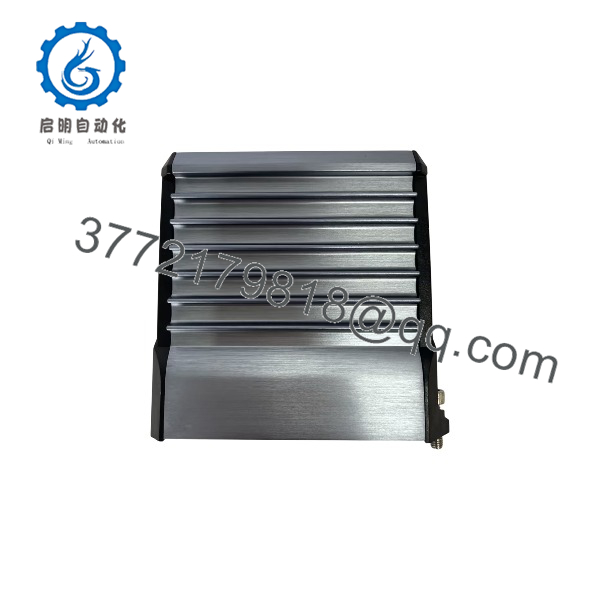
FBM219
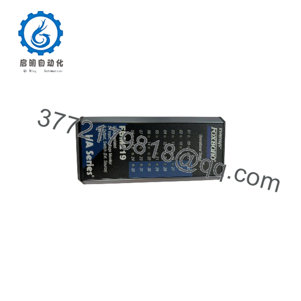
FBM219
Troubleshooting Quick Reference
| Symptom | Possible Cause | Relevance to This Part | Quick Check Method | Recommendation |
|---|---|---|---|---|
| All 24 inputs and 8 outputs show bad quality or module is absent | Loss of redundant 24 V DC supply, fieldbus fault, baseplate problem, loose module, failed FBM219 | ✅ High | Check DCS module diagnostics. Measure redundant 24 V DC at the baseplate and verify communication to the associated FCM or FCP. Inspect module seating and connector condition under an approved maintenance procedure. | Correct power, fieldbus, or baseplate faults before replacing the . A total I/O loss usually has a common cause. |
| One discrete input stays OFF with field device energized | Open field conductor, blown fuse, failed contact, low input voltage, incorrect termination assembly, failed channel | ⚠️ Medium | Measure voltage at the specific TA input terminal. For standard DC monitoring, verify 15–30 V DC for an ON state. Check the field device and common return. | Repair the field circuit before replacing the card. A valid voltage must be present at the correct TA terminal before the module becomes suspect. |
| One input stays ON after contact opens | Welded auxiliary contact, shorted cable, moisture ingress, terminal cross-wire, TA fault, failed input channel | ⚠️ Medium | Under approved conditions, remove the field conductor at the TA. If the DCS point remains ON, inspect the TA and input channel. If it goes OFF, troubleshoot the field circuit. | Isolate the field wiring before replacing the . |
| DCS output command is ON but relay or solenoid does not energize | Field power absent, output fuse open, open coil, external-source wiring fault, load exceeds 0.25 A, failed output channel | ⚠️ Medium | Confirm the DCS command. Measure switched voltage at the TA output and at the field load. Measure coil resistance and verify external field supply. | Diagnose the field circuit first. The standard output is limited to 60 V DC and 0.25 A per channel; do not use it as a high-current power source. |
| Output remains energized after DCS turns it OFF | Welded interposing relay, field wiring short, external-source feedback path, failed output transistor or TA relay | ⚠️ Medium | Remove the output command, measure voltage at the TA, and isolate the load under approved procedure. Check for backfeed from another supply and inspect relay contacts. | Identify any external backfeed or welded relay before replacing the module. |
| Several outputs fail simultaneously | External field supply loss, fuse group open, shared common fault, overloaded power supply, TA connector issue | ⚠️ Medium | Check the external output supply, fuse holders, common return, TA connector, and output-load current. Compare several affected output terminals. | Fix shared output power or wiring faults before replacing . |
| Outputs chatter or card area runs hot | Supply voltage sag, inductive loads without suppression, loose terminals, overloaded output, shorted solenoid coil | ✅ High | Monitor field supply during switching. Confirm output current stays below 0.25 A. Inspect flyback diodes, RC snubbers, terminal torque, and load resistance. | Correct the load circuit before installing a replacement. An unresolved coil or suppression fault can damage the next module. |
| I/O states are wrong after a replacement | Incorrect part/revision, wrong TA, reversed connector, DCS configuration mismatch, field terminals moved incorrectly | ✅ High | Compare old and new labels: , P0916RH, RH916RH, revision, and TA identity. Verify DCS database assignment, output type, and all terminals against drawings. | Do not wire from memory. Perform a 32-point input/output checkout before returning the system to automatic operation. |
Field note: The first thing to check on an output problem is external power. The module switches an external source; it does not create field power. I have seen a full card swapped because eight outputs were dead, when the real fault was a single blown fuse feeding the output common.
For support, provide photos of the front and side label, P0916RH or RH916RH marking, termination assembly, baseplate, output fuse block, DCS diagnostics, measured input/output voltage, and the I/O loop drawing.
Frequently Asked Questions
What does the Foxboro do?
The is a discrete I/O interface module with 24 inputs and 8 outputs. It reads voltage or contact-related field status signals and switches compatible discrete loads through matched Foxboro termination assemblies. Common uses include valve feedback, motor starter status, alarm contacts, relays, solenoids, and permissive circuits.
Is the same as RH916RH?
supersedes the legacy identifier for the assembly. Verify the actual module label, revision, and associated termination assembly before ordering. A supersession does not remove the need to check electrical compatibility, field wiring, and DCS configuration.
How many inputs and outputs does have?
The provides 24 group-isolated discrete input channels and 8 group-isolated discrete output channels. It is not an analog I/O module. Any listing that calls it “analog I/O” is inaccurate for the documented function.
What output load can an switch?
For the standard external-source output configuration, each output can switch up to 60 V DC at 0.25 A. Higher-voltage or higher-current field circuits require the correct Foxboro termination assembly and, in many applications, an interposing relay. Do not connect a large solenoid, contactor coil, or motor-control load directly to a standard output without checking the complete termination and load specification.
Can handle 120 V AC, 125 V DC, or 240 V AC field circuits?
Yes, but only with the correct Foxboro termination assembly. The module is paired with TAs that provide the needed voltage adaptation, current limiting, fuse protection, relay interface, and isolation for the connected field circuits. Do not infer field-voltage capability from the module alone.
Can I hot-swap an ?
Follow the approved Foxboro DCS maintenance procedure and the site’s process-safety rules. Do not treat this as a casual hot-swap. Removing the module may affect 24 status inputs and eight live output commands. That can produce alarm floods, stop equipment, energize or de-energize field devices according to configured fault behavior, or interfere with interlocks.
Before replacement, identify every affected point, notify operations, put controlled equipment in a safe state, manage alarms and bypasses through an approved procedure, document field terminals, and use a grounded ESD wrist strap.
Why does my output not turn on?
Use this sequence:
- Confirm the DCS logic commands the output ON.
- Check the module and DCS diagnostics for output fault or bad quality.
- Measure external field power and check the output fuse.
- Measure switched voltage at the termination-assembly output terminal.
- Measure voltage at the relay or solenoid coil.
- Check coil resistance, return path, and wiring continuity.
- Verify the load does not exceed 60 V DC or 0.25 A for the standard output switch.
If external power is healthy and the does not switch a known-good test load, the output channel or termination assembly is a credible failure point.
Why are all eight outputs dead but inputs still work?
This usually points to a shared external output-side issue, not the entire . Check the output power supply, fuse block, shared output common, termination-assembly connector, and any interposing-relay supply. The inputs and outputs use different field circuits, so working inputs do not prove that the output supply is present.
Is this New Surplus or Refurbished?
The product condition must be stated clearly on the quote. New Original / New Surplus means unused legacy inventory with documented labeling, connector condition, and storage inspection. Refurbished (tested) means a used module that has been inspected, powered, and functionally tested.
For a refurbished , request actual-unit photos, or label verification, 24 V DC power-on testing, fieldbus communication verification, 24-input voltage simulation, eight-output switching tests with documented voltage/current loads, connector inspection, and a written test report. Test videos and photos should be available upon request.
What should I verify before ordering an replacement?
- Exact label: , or , and hardware revision
- I/A Series baseplate and FCM/FCP communication architecture
- Termination assembly part number and connector orientation
- Input field voltage and required contact/voltage-monitor function
- Output field voltage, current, fusing, and external-source arrangement
- Inductive load suppression for relays, solenoids, and contactor interfaces
- DCS database configuration, output fail behavior, and diagnostic history
- Existing input/output field wiring and shared common paths
- Required condition: New Original/New Surplus or Refurbished (tested)
Keep these checks in mind and you will avoid most replacement rework.



