
 WhatsApp: +86 16626708626
 Email:
  Phone: +86 16626708626
Description
Key Technical Specifications
| Parameter | Value |
|---|---|
| Product Model | FBM230 |
| Ordering Number | P0926GU |
| Manufacturer | Foxboro (Invensys / Schneider Electric) |
| System Platform | Foxboro I/A Series DCS / Foxboro Evo |
| Product Type | Field Device System Integrator (FDSI) Module |
| Communication Ports | 4 independent serial ports |
| Serial Interface | RS-232, RS-422, RS-485 |
| Port Configuration | Software configurable per port |
| Communication Protocols | Modbus RTU, Modbus ASCII, vendor-specific serial protocols (driver dependent) |
| Network Topology | Point-to-point and RS-485 multidrop |
| Maximum RS-485 Devices | Up to 64 field devices (configuration dependent) |
| Fieldbus Communication | Redundant 2 Mbps I/A Series Fieldbus |
| Host Interface | FCP270, FCP280, ZCP270, FCM100E/FCM100Et |
| Isolation | Serial port electrical isolation |
| Baud Rate | Protocol and driver dependent |
| Termination Assembly | Dedicated FBM230 TA assembly |
| Power Supply | 24 V DC +5 %, −10 % redundant input |
| Power Consumption | 7 W maximum |
| Heat Dissipation | 7 W maximum |
| Operating Temperature | −20 to +70 °C |
| Storage Temperature | −40 to +70 °C |
| Relative Humidity | 5 to 95 % RH, non-condensing |
| Mounting | Foxboro I/A Series 200 baseplate |
| Dimensions | 102 mm × 45 mm × 104 mm |
| Weight | Approximately 284 g |
The Foxboro FBM230 P0926GU is a Field Device System Integrator module providing four configurable serial communication ports for integrating third-party devices into Foxboro I/A Series systems. Each port can be configured for RS-232, RS-422, or RS-485 communication standards.
Product Introduction
The Foxboro FBM230 P0926GU is a serial communication interface module used in I/A Series DCS installations to connect external field devices through RS-232, RS-422, or RS-485 networks. Typical applications include Modbus RTU meters, analyzers, motor drives, PLCs, and packaged equipment controllers.
The module provides four independent serial channels and transfers device data between third-party equipment and the Foxboro control system. It is commonly retained in operating plants where legacy serial instruments must remain integrated without replacing the complete DCS architecture.
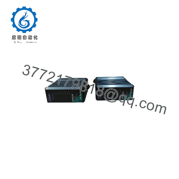
FBM230
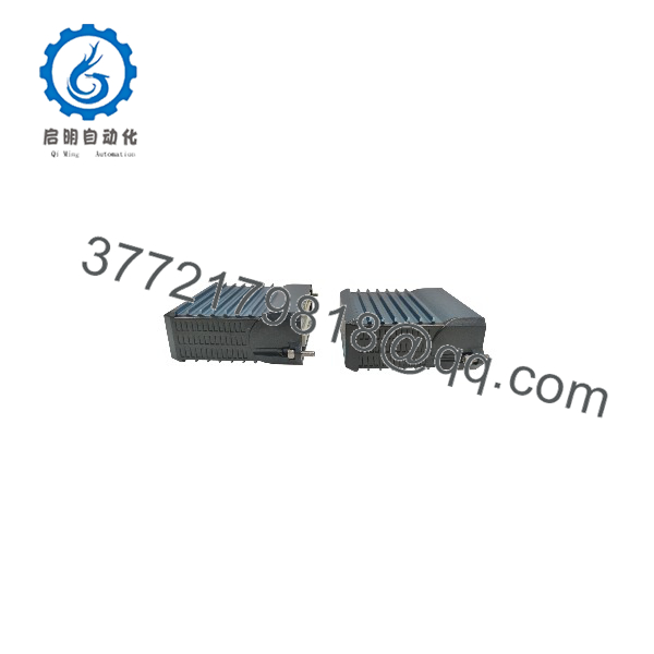
FBM230
Installation & Configuration Guide
Stage 1: Pre-Installation Preparation (Approx. 15 minutes)
⚠️ Safety First
- Notify the control room before removing the FBM230.
- Confirm affected serial-connected devices can tolerate communication interruption.
- Place critical equipment into a safe operating state.
- Apply lockout/tagout procedures if cabinet power isolation is required.
- Wait at least 5 minutes after power removal before handling the module.
Tools Required
- ESD wrist strap
- PH1 screwdriver
- Digital multimeter
- Wire labels
- Smartphone for photos
- Serial communication tester (recommended)
Data Backup
Before removal:
- Record:
- FBM230 model and P0926GU part number
- Module slot location
- Serial port assignments
- Protocol configuration
- Photograph:
- Terminal wiring
- Shield grounding
- RS-485 termination resistors
- Cable routing
- Save:
- Device driver configuration
- Modbus addresses
- Baud rate settings
- Data mapping tables
Stage 2: Removing the Old Module (Approx. 10 minutes)
Steps
- Open the Foxboro I/A Series cabinet.
- Confirm the correct slot.
- Label each serial communication cable.
- Disconnect wiring from the termination assembly.
- Release the module locking mechanism.
- Pull the straight outward from the baseplate.
- Inspect:
- Backplane connector pins
- Cable connectors
- Dust contamination
- Mechanical damage
⚠️ Note:
Keep the old until communication testing is complete. Serial communication failures are often caused by configuration differences rather than hardware faults.
Stage 3: Installing the New Module (Approx. 15 minutes)
Steps
- Wear an ESD strap before handling the replacement module.
- Verify:
- model
- P0926GU ordering code
- Compatible termination assembly
- Correct serial driver support
- Configuration Clone (Critical):
- Match port assignments.
- Copy RS-232/422/485 settings.
- Verify baud rate.
- Verify parity and stop bits.
- Confirm device addresses.
- Check RS-485 termination.
- Insert the into the baseplate.
- Secure module locking tabs.
- Reconnect communication wiring.
Self-Checklist
- P0926GU confirmed
- Serial ports mapped correctly
- RS-485 termination verified
- Shield grounding checked
- Module seated correctly
Stage 4: Power-On & Testing (Approx. 20 minutes)
Pre-Power Check
- Verify 24 V DC supply.
- Check serial wiring polarity.
- Confirm RS-485 A/B lines are not reversed.
- Verify communication grounding.
Power-On Steps
- Restore cabinet power.
- Check status LEDs.
- Verify Fieldbus communication.
- Confirm module status in Foxboro system management tools.
- Test serial communication.
- Verify device data updates.
- Confirm control logic receives correct values.
⚠️ Troubleshooting Note
- If communication fails, check baud rate, parity, and address settings first.
- If only one direction works, inspect RS-485 polarity and termination.
- If the module is online but data is incorrect, verify device register mapping.
Frequently Asked Questions (FAQ)
Q1: Can the Foxboro be hot-swapped?
The replacement procedure depends on the specific I/A Series hardware configuration and plant maintenance rules.
Although some I/A Series systems support online module replacement, serial-connected field devices may lose communication during removal. Confirm the site procedure before replacing an active module.
Q2: What devices can connect to the ?
The connects Foxboro I/A Series systems with serial field devices such as:
- PLCs
- Power meters
- Analyzers
- Variable frequency drives
- Package equipment controllers
- Remote serial instruments
The actual protocol depends on the installed software driver and device configuration.
Q3: Is the obsolete?
The belongs to the mature Foxboro I/A Series hardware family. Many plants continue using these systems, so replacement modules remain required for maintenance and spare inventory management. Availability depends on remaining stock and tested units.
Q4: Are and FBM231 interchangeable?
No.
The is designed for single serial communication applications. The FBM231 provides a redundant version for dual-ported field devices.
Before replacement, verify:
- Module model
- Redundancy requirement
- Serial port configuration
- Field device communication architecture
Q5: Will replacing the erase my Modbus configuration?
No. The Foxboro control database stores the system configuration, but the replacement module requires correct communication parameters.
Verify:
- Protocol driver
- Device address
- Baud rate
- Data register mapping
- Port configuration
A hardware replacement without configuration verification can result in communication timeouts.
Q6: Why is surplus pricing lower than OEM pricing?
Legacy automation modules often enter the market through:
- Plant shutdown inventory
- DCS upgrade projects
- Excess engineering stock
- Maintenance spare liquidation
Condition should always be clearly identified:
- New Original / New Surplus: Unused inventory.
- Factory Sealed: Original unopened packaging when available.
- Refurbished (tested): Inspected and function-tested before shipment.
Q7: What inspection process should be completed before installing a surplus ?
Inbound Inspection & Traceability
- Verify source documentation.
- Confirm and markings.
- Check serial numbers.
- Inspect enclosure condition.
- Confirm no corrosion, scratches, repair marks, or contamination.
- Audit accessories.
Live Functional Testing
Test environment:
- Genuine Foxboro I/A Series FBM test rack.
Testing steps:
- Power-up LED verification.
- Fieldbus communication test.
- RS-232 communication test.
- RS-485 communication test.
- Modbus data exchange verification.
- Continuous operation monitoring.
- Test report generation.
Electrical Parameter Testing
- Insulation resistance test using 500 V Megger where applicable.
- Ground continuity check.
- Serial port isolation verification.
Firmware & Configuration Verification
- Record hardware revision.
- Document module identification.
- Save communication configuration.
- Photograph labels and connectors.
Final QC & Packaging
- QC inspector sign-off.
- Anti-static ESD bagging.
- Bubble wrap protection.
- Heavy-duty corrugated boxing.
- QC Passed label with inspection date.
Q8: What are the most common replacement mistakes?
❗ The most common mistake is replacing the module without documenting serial communication settings.
I have seen maintenance teams install a replacement correctly, but the connected PLC or analyzer would not communicate because the old RS-485 parameters were not recorded.
Common issues:
- Wrong baud rate.
- Incorrect parity settings.
- RS-485 polarity reversed.
- Missing termination resistor.
- Incorrect Modbus register mapping.
Take photos before removal and record every communication parameter. Those checks prevent most serial integration delays.



