
 WhatsApp: +86 16626708626
 Email:
  Phone: +86 16626708626
Description
Key Technical Specifications
| Parameter | Value |
|---|---|
| Manufacturer | Foxboro, formerly Invensys Process Systems; now part of Schneider Electric |
| Module designation | FBM242 |
| Assembly part number | P0916TA |
| Product family | Foxboro I/A Series / EcoStruxure Foxboro DCS |
| Product type | Externally sourced discrete output interface module |
| Output channels | 16 fully isolated discrete output channels |
| Field-power arrangement | External power supply energizes field circuits |
| Standard applied output voltage | 15–60 V DC maximum |
| Standard continuous load current | 2.25 A maximum per channel |
| Common sales rating | Up to 2 A per output at 60 V DC |
| Inrush current at 30 °C | 8 A maximum for 20 ms per channel |
| Inrush current at 70 °C | 6.4 A maximum for 20 ms per channel |
| On-state voltage drop | 0.2 V maximum at 2.25 A |
| Off-state leakage current | 0.1 mA maximum |
| Channel isolation | Each output galvanically isolated from every other output and ground |
| Isolation withstand | 600 V AC for 1 minute, channel-to-channel and channel-to-ground |
| Supported higher-voltage interfaces | 120 V AC / 125 V DC and 240 V AC through the correct Foxboro termination assembly and relay interface |
| Inductive-load protection | External diode for DC coils or MOV/snubber for AC loads may be required |
| Output modes | Sustained or momentary output; configurable through the I/A Series application |
| Fault behavior | Supports configurable fail-safe configuration and fail-safe fallback |
| Logic support | Executes Discrete I/O or Ladder Logic application program |
| Redundant module supply | 24 V DC, +5% / −10% |
| Maximum module power consumption | 3 W at 24 V DC |
| Maximum heat dissipation | 6.5 W at 24 V DC with all outputs at 1.5 A |
| Operating temperature | −20 to +70 °C (−4 to +158 °F) |
| Relative humidity | 5–95%, noncondensing |
| Environmental classification | ISA S71.04 Class G3 harsh industrial environment |
| Calibration requirement | No module or termination-assembly calibration required |
| Replacement requirement | Match FBM242/P0916TA, terminal assembly, output voltage, load current, inrush, fail-state configuration, and field wiring |
The Foxboro FBM242 P0916TA has 16 externally powered, isolated discrete outputs. Its standard DC output circuit supports 15–60 V DC with up to 2.25 A per channel, while matching termination assemblies provide interfaces for 120 V AC/125 V DC or 240 V AC relay circuits. Each channel is isolated from other channels and ground.
Product Introduction
The Foxboro FBM242 P0916TA is a 16-channel externally sourced discrete output module for Foxboro I/A Series and EcoStruxure Foxboro DCS systems. It switches externally powered field loads such as solenoid valves, relay coils, alarms, annunciators, interposing relays, and low-power actuator circuits.
The FBM242 does not generate field power. It switches an external source through each output channel. That distinction matters during troubleshooting: a dead 24 V DC output supply, blown fuse, overloaded coil, or missing suppression device can look like a module failure. Match the P0916TA module, termination assembly, output load, and configured fail behavior before replacement.
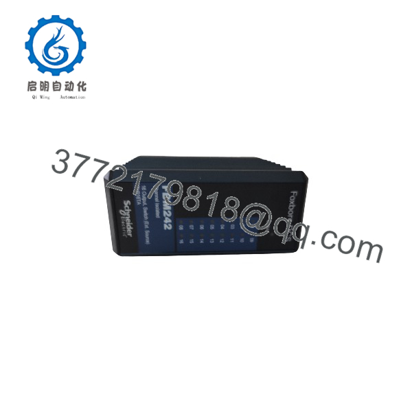
FBM242
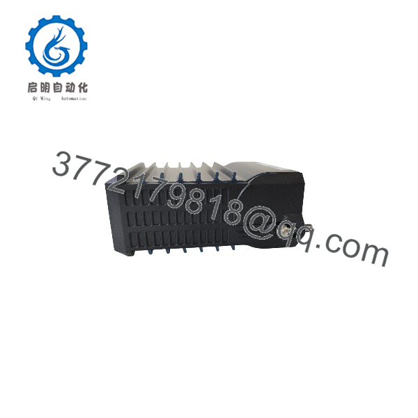
FBM242
Troubleshooting Quick Reference
| Symptom | Possible Cause | Relevance to This Part | Quick Check Method | Recommendation |
|---|---|---|---|---|
| All 16 outputs are unavailable or module is absent | Loss of redundant 24 V DC module supply, baseplate or module-fieldbus issue, poor module seating, failed FBM242 | ✅ High | Check DCS hardware diagnostics first. Measure redundant 24 V DC at the baseplate and verify communication to the associated FCM or FCP. Inspect module seating and contacts under approved isolation. | Restore module power, fieldbus, or baseplate integrity before replacing the . |
| All outputs are commanded ON but field loads remain de-energized | External field-power supply off, shared fuse open, output common disconnected, terminal assembly issue | ✅ High | Measure external supply voltage at the termination assembly. Check fuse blocks, output commons, and field-power disconnects. Compare voltage at more than one output terminal. | Restore external field power first. The switches an external supply; it cannot energize a load if the source is missing. |
| One output is ON in DCS but solenoid or relay does not energize | Open coil, failed field wiring, blown branch fuse, loose terminal, load current too high, failed output channel | ⚠️ Medium | Confirm DCS command. Measure switched voltage at the termination output, then at the load. Measure coil resistance and current. | Repair the external load circuit before replacing the card. Replace the channel only if it fails to switch a known-good test load. |
| Output remains ON after DCS command goes OFF | Welded external relay, backfeed from another power source, wiring short, failed output transistor, incorrect logic configuration | ⚠️ Medium | Remove the command and measure output voltage. Isolate the field load under approved procedure. Check for reverse/backfeed voltage and inspect interposing relay contacts. | Eliminate external backfeed and verify logic before replacing . |
| Output chatter or drops out under load | Power supply sag, loose common, undersized cable, high inrush, coil fault, inductive kickback, poor suppression | ⚠️ Medium | Monitor external field supply while the load operates. Measure output current and compare with 2.25 A maximum. Inspect diode, MOV, or RC snubber condition. | Correct supply and load issues before replacing hardware. Repeated inductive transients can damage a replacement output. |
| Module or termination area overheats | Output overload, sustained high current, shorted solenoid, loose terminal, damaged suppression device | ✅ High | Make the circuit safe. Check channel current, coil resistance, cable insulation, terminal torque, and visible heat discoloration. Verify no channel exceeds 2.25 A continuous load. | Remove the overload and inspect the termination assembly before installing another module. |
| Output fault appears after replacement | Wrong module or termination assembly, incorrect output mapping, fail-safe setting mismatch, field wires transferred incorrectly, ESD damage | ✅ High | Compare old and replacement labels: and P0916TA. Verify TA part number, DCS database assignment, output type, output mode, and configured fail-safe behavior. | Do not wire from memory. Function-test all 16 channels during commissioning. |
| New module fails immediately on a coil circuit | No flyback diode on DC coil, incorrect diode polarity, missing MOV/snubber on AC load, inrush beyond rating, supply miswiring | ✅ High | Inspect every inductive load. For DC coils, verify a correctly oriented protective diode across the coil. For AC loads, verify approved MOV or RC suppression. Measure startup inrush. | Correct suppression before reconnecting a replacement. I have seen an output card fail repeatedly because one solenoid coil had no suppression device. |
Field note: The is a high-current discrete output module, so the usual failure is outside the card: a shorted coil, an overloaded branch, a loose common, or no surge suppression. Measure current before replacing it. If a 24 V DC solenoid repeatedly eats output channels, inspect the flyback diode before you blame the DCS.
If the fault remains unclear, provide the / label photo, termination assembly number, module diagnostics, external supply voltage, output current, coil resistance, photos of suppression devices, and the relevant I/O loop drawing.
Frequently Asked Questions
What does the Foxboro do?
The is a 16-channel externally sourced discrete output module. It lets a Foxboro I/A Series or EcoStruxure Foxboro DCS switch compatible field loads using an external power supply. Typical loads include solenoid valves, relay coils, alarm horns, lamps, and interposing relays.
Does provide its own output power?
No. The module switches an external field power source. You must verify the external supply, fuse protection, output common, load wiring, and termination assembly. If all outputs are dead, start by measuring the external field supply at the termination assembly—not by replacing the .
What load can each output handle?
For standard DC service, each output supports 15–60 V DC and up to 2.25 A continuous current. Each channel can handle up to 8 A for 20 ms at 30 °C, or 6.4 A for 20 ms at 70 °C. Use the actual plant ambient temperature and inrush profile when evaluating a solenoid or relay load.
Can I connect 120 V AC, 125 V DC, or 240 V AC loads?
Yes, but not directly on the standard DC output interface. Use the correct Foxboro termination assembly and relay interface. The termination assembly provides the appropriate field-voltage interface, relay contacts, fuse arrangement, and isolation. Do not connect a high-voltage load based solely on the module label.
Does each output have isolation?
Yes. Each output is galvanically isolated from every other channel and from ground. The documented isolation withstand is 600 V AC for one minute. This helps limit cross-channel fault propagation, but it does not remove the need for proper fusing, grounding, and surge suppression in the field circuit.
Can I use to drive inductive loads?
Yes, if you provide the correct suppression and stay inside the electrical ratings. For DC coils, use a properly oriented flyback diode across the coil. For AC coils, use an approved MOV or RC snubber. Without suppression, the voltage spike generated when the coil de-energizes can damage the output circuit.
Do not skip this step. I once saw a replacement output module fail on the first shift because the original solenoid had a missing diode and the cabinet had no spare suppression parts.
Can I hot-swap an ?
Follow the approved Foxboro DCS maintenance procedure and site operating rules. Do not assume removal is harmless. Pulling an output module can de-energize or alter 16 field outputs, affecting valves, relays, alarms, equipment permissives, and shutdown-related logic.
Before removal, identify every output and its field effect, put equipment in an approved safe state, notify operations, manage bypasses only through formal authorization, isolate field power where required, document wiring, and use a grounded ESD wrist strap.
Why is an output ON in the DCS but no field device operates?
Check these items in order:
- Confirm the output command is actually ON in the DCS logic.
- Measure external field supply at the termination assembly.
- Check output fuses and shared output common.
- Measure switched voltage at the specific output terminal.
- Measure voltage at the load coil.
- Check coil resistance and cable continuity.
- Confirm the load is below 60 V DC and 2.25 A per channel.
- Verify suppression-device condition and polarity.
If the module does not switch voltage to a known-good, correctly wired, low-current test load, the output channel or termination assembly is a credible failure point.
Is this New Surplus or Refurbished?
The offered condition must be explicit. New Original / New Surplus means unused legacy stock with verified identity labels, clean connectors, and documented storage inspection. Refurbished (tested) means a previously used module that has been inspected, cleaned, powered, and functionally tested.
For a refurbished , request actual-unit photos, label verification, 24 V DC power-on result, fieldbus communication test, 16-channel output switching results, test voltage/current for each output, inspection of terminals and connectors, and a written test report. Test videos and photos should be available upon request.
What should I verify before ordering an replacement?
- Exact module label: and
- I/A Series baseplate, fieldbus architecture, and DCS database assignment
- Associated termination assembly part number and connector orientation
- External field supply voltage, fuse rating, and shared output common
- Load voltage, steady-state current, and measured inrush current
- Presence and condition of flyback diodes, MOVs, or RC snubbers
- Output mode: sustained or momentary
- Configured fail-safe state and fallback behavior
- Existing module diagnostics, output status, and field-loop test results
- Required condition: New Original/New Surplus or Refurbished (tested)
Keep these checks in mind and you will avoid most replacement rework.



