
 WhatsApp: +86 16626708626
 Email:
  Phone: +86 16626708626
Description
Key Technical Specifications
| Parameter | Value |
|---|---|
| Manufacturer | Foxboro |
| Model | FBM242 |
| Part Number | P0916NG |
| Product Category | Discrete Output Termination Assembly |
| Control System | Foxboro I/A Series |
| Output Channels | 16 channels |
| Output Type | SPDT (Form C) relay outputs |
| External Source Voltage | Up to 250 V AC / 125 V DC (application dependent) |
| Relay Contact Rating | Up to 5 A at 250 V AC |
| DC Switching Capability | <30 V DC at 5 A maximum |
| Isolation | Channel isolation provided by termination assembly relays |
| Field Connection | Compression terminal interface |
| Mounting Method | DIN rail mounted termination assembly |
| Communication Interface | Via FBM242 module through redundant 2 Mbps Fieldbus |
| Environmental Rating | Suitable for Class G3 harsh environments |
| Operating Temperature | FBM242 system: approximately -20 to +70 °C |
| Module Power Supply | 24 V DC redundant supply system |
| Calibration | No calibration required |
Product Introduction
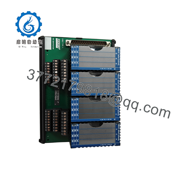
The Foxboro FBM242 P0916NG is a termination assembly used with the FBM242 externally sourced discrete output interface module in Foxboro I/A Series DCS installations. It provides 16 relay output channels for controlling external field loads such as motor starters, solenoid valves, alarms, and other discrete devices.
The P0916NG termination assembly handles field-side switching through SPDT relay contacts while maintaining electrical separation between control electronics and external circuits. It is commonly retained by plants operating legacy I/A Series systems where replacing the complete DCS platform is not practical.
Installation & Configuration Guide
Stage 1: Pre-Installation Preparation (Estimated Time: 10 minutes)
⚠️ Safety First
Before replacing the FBM242 P0916NG:
- Notify operations and obtain shutdown approval.
- Place controlled equipment into a safe state.
- Apply lockout/tagout procedures.
- Verify field power isolation with a multimeter.
Tools Required
- ESD wrist strap
- Digital multimeter
- PH1 screwdriver
- Wire labels
- Smartphone/camera for documentation
Data Backup
Before removal:
- Record the module slot location.
- Photograph all relay wiring.
- Document terminal numbering.
- Record field device assignments.
- Verify I/A Series configuration database mapping.
Stage 2: Removing the Existing Assembly (Estimated Time: 15 minutes)
- Remove cabinet access covers.
- Identify the P0916NG termination assembly.
- Label all field wiring before disconnecting.
- Loosen compression terminals carefully.
- Disconnect field wiring.
- Remove termination assembly mounting hardware.
- Inspect DIN rail mounting area.
⚠️ Important:
Do not rely on memory for relay terminal wiring. A single misplaced common contact can reverse equipment operation.
Stage 3: Installing the New P0916NG (Estimated Time: 15 minutes)
- Confirm the replacement part:
Foxboro →
- Verify compatibility with the existing module.
- Mount the termination assembly on the DIN rail.
- Reconnect wiring according to the original documentation.
- Check relay common, normally open (NO), and normally closed (NC) terminals.
- Tighten terminals to the recommended torque.
Installation Checklist
☐ Correct TA model installed
☐ Relay wiring verified
☐ Field voltage confirmed
☐ Ground connections checked
☐ Terminal screws secured
Stage 4: Power-On & Functional Testing
- Restore control cabinet power.
- Verify communication status.
- Confirm module recognition in the Foxboro I/A Series system.
- Test individual output channels.
Recommended checks:
- Command output ON/OFF from control system.
- Verify relay contact changeover.
- Confirm field device response.
- Check abnormal alarms.
⚠️ Troubleshooting Note
If output commands appear correct but equipment does not respond:
- Check external field power.
- Verify relay common and NO/NC wiring.
- Confirm the correct termination assembly model.
- Check whether the field load exceeds relay ratings.
Frequently Asked Questions (FAQ)
Q1: Is Foxboro a complete I/O module?
No. The is the termination assembly used with the discrete output interface module. The electronics and the termination assembly work together as an I/O channel system.
Q2: What type of signals does the handle?
The system handles discrete output signals. The termination assembly provides SPDT relay contacts for externally sourced field loads.
Q3: Can the replace other termination assemblies?
Not always. Foxboro provides multiple termination assemblies with different protection, relay, and power distribution arrangements. Verify the exact TA part number before ordering.
Q4: Is obsolete?
The Foxboro I/A Series FBM family is a legacy control platform. Many plants still operate these systems, so replacement parts are commonly sourced through industrial automation inventory suppliers. Confirm availability and condition before purchase.
Q5: Does replacing require software changes?
Usually, no major software modification is required if the replacement uses the same termination assembly type and wiring arrangement. However, verify the configuration and channel assignments before returning the system to service.
Q6: Why is this part available below original OEM pricing?
Legacy Foxboro components are often supplied from:
- New surplus inventory
- Factory spare stock
- Tested refurbished inventory
Always confirm:
- Physical condition
- Test documentation
- Warranty coverage
- Packaging status
Q7: What should be checked before ordering ?
Confirm:
- Existing module:
- Termination assembly:
- Relay output requirements
- Field voltage level
- Terminal wiring arrangement
- Existing Foxboro I/A Series hardware revision
Incorrect termination assembly selection can result in wiring changes and commissioning delays.



