
 WhatsApp: +86 16626708626
 Email:
  Phone: +86 16626708626
Description
3. Key Technical Specifications
| Parameter | Value |
|---|---|
| Module | FBM242 – 16 isolated discrete outputs (externally sourced) |
| Termination Assembly | RH916YY (supersedes P0916YY / P0916NG) – Compression type |
| Output Type (via TA) | SPDT (Form C) relays |
| Relay Ratings | <30 V DC at 5 A max; 125 V DC at 600 mA resistive / 250 mA inductive; up to 250 V AC at 5 A max |
| Total Current Limit | 12 A maximum per group of 8 channels simultaneously |
| Isolation | Channel isolation provided by TA relays; module provides galvanic isolation |
| Applied Voltage (Module) | 15–60 V DC max (external source) |
| Module Load Current | 2.25 A max per channel (when used with solid-state TAs) |
| Power Supply (Module) | 24 V DC +5% / –10% |
| Power Consumption (Module) | 3 W maximum at 24 V DC |
| Operating Temperature | –20 to +70 °C (–4 to +158 °F) |
| Relative Humidity | 5 to 95% (non-condensing) |
| Communication | Module Fieldbus to FCM / FCP |
| Application Programs | Discrete I/O or Ladder Logic with Fail-Safe, Sustained/Momentary options |
| Environment | Class G3 (harsh) per ISA S71.04 |
4. Product Introduction
The Foxboro FBM242 with RH916YY Termination Assembly provides 16 channels of externally sourced discrete output for the I/A Series and EcoStruxure Foxboro DCS. The FBM242 module switches the field signals while the RH916YY TA converts those signals through SPDT (Form C) relays, allowing direct control of higher-voltage AC or DC loads such as motor starters, solenoids, and contactors.
The RH916YY supports up to 5 A at 30 V DC or 250 V AC per channel (with a 12 A group limit) and supplies channel isolation through the relays. The combination mounts on standard 200 Series baseplates, executes Discrete I/O or Ladder Logic programs with configurable Fail-Safe behavior, and is rated for Class G3 environments from –20 to +70 °C.
5. Troubleshooting Quick Reference
| Symptom | Possible Cause | Relevance to this Part | Quick Check Method | Recommendation |
|---|---|---|---|---|
| No outputs switch | Module power loss or Fieldbus failure | ✅ High | Measure 24 V DC at module power terminals; check Fieldbus LEDs and status in system software | Confirm 24 V supply and Fieldbus path before replacing module or TA |
| Single channel will not energize | Failed relay on RH916YY, open field wiring, or channel fault | ✅ High | Force channel ON in software; listen for relay click and measure voltage at TA field terminals | If no relay action, replace RH916YY TA; if relay clicks but no field voltage, check external power and wiring |
| Output chatters or intermittent | Inductive load without suppression or weak external supply | ✅ Medium | Verify snubber/diode across inductive loads; measure external supply under load | Add proper suppression; confirm external field power capacity |
| All outputs drop on power cycle | Fail-Safe configuration set to de-energize | ❌ Low | Review Fail-Safe and fallback settings in control blocks | This is configuration, not hardware failure; set desired hold or fallback state |
| Module online but relays stay open | Incorrect TA wiring or missing external field power | ✅ High | Confirm external power is present at TA power distribution terminals; check for blown fuses if present | Isolate and restore field power; verify is the correct relay TA |
| Module fails to come online | Fieldbus path or baseplate slot issue | ❌ Low | Move module to known-good slot; verify Fieldbus continuity | Problem is usually upstream of the FBM242; check Fieldbus first |
If diagnostics remain unclear, capture module status LEDs, diagnostic buffer screenshots, TA photos, and external supply measurements, then contact technical support with the exact part numbers and system software version.
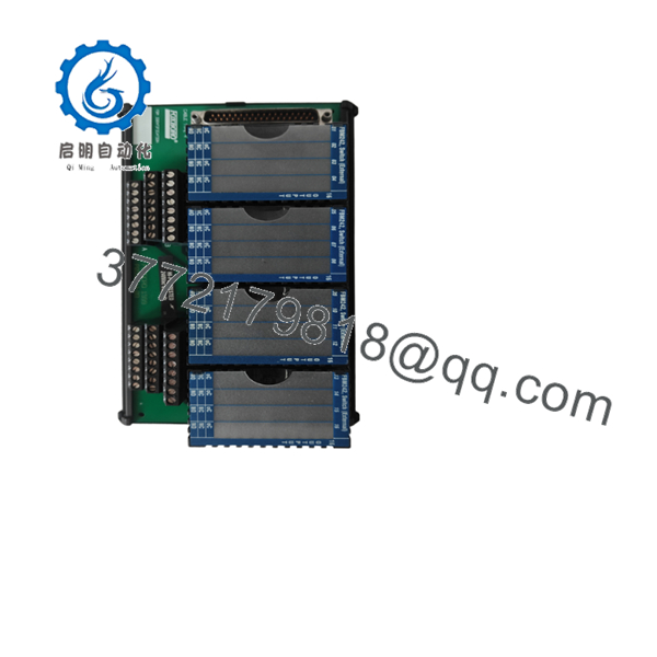
- FBM242
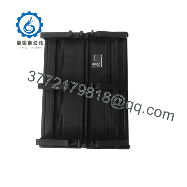
- FBM242
6. Frequently Asked Questions (FAQ)
Q: Is the + hot-swappable? No. Isolate field power and remove module power before insertion or removal. Hot-swapping risks backplane damage and uncontrolled field device states.
Q: What is the difference between and other TAs? uses SPDT (Form C) relays for higher voltage/current switching (up to 5 A @ 250 V AC or 30 V DC). Other TAs provide solid-state switching limited to lower voltages (typically 15–60 V DC at 2 A) or different fuse/power-distribution options. Confirm the TA matches your load voltage and current requirements.
Q: Does the module itself need an external power supply? Yes. The outputs are externally sourced. The TA requires a separate field power supply for the relay contacts. The module only needs 24 V DC for its logic and Fieldbus interface.
Q: Can I use the for both AC and DC loads? Yes. The Form C relays support mixed AC and DC loads within the published ratings. Keep total current within the 12 A limit per group of eight channels and apply proper suppression for inductive loads.
Q: Why is new surplus pricing lower than current Schneider list? These are genuine OEM modules and termination assemblies from excess or decommissioned stock. They have not seen continuous field service. Every unit undergoes inbound inspection, power-up, and functional testing on a Foxboro I/A Series rack before shipment. Test reports are available on request.
Q: Does this combination support momentary (pulsed) outputs? Yes. In Ladder Logic or Discrete I/O applications you can configure sustained or momentary outputs. When momentary is selected, the pulse interval is also configurable.
Q: What happens on communication loss or power failure? Behavior is set by the Fail-Safe configuration in the control blocks. Common options are hold last state or go to a predefined fallback (usually de-energized). Document the existing settings before replacement so the new module matches site requirements.



