
 WhatsApp: +86 16626708626
 Email:
  Phone: +86 16626708626
Description
Key Technical Specifications
| Parameter | Specification Value |
| Part Number | RH914YZ (RoHS-compliant version of P0914YZ) |
| Module Type | Fieldbus Communications Module (Baseplate Extension Coupler) |
| Fiber Interface | Duplex ST connectors (62.5/125 µm multi-mode fiber optic cable) |
| Fiber Transmission Distance | Up to 2,000 meters (2 km / 6,500 feet) between baseplates |
| Fieldbus Speed | 2 Mbps redundant Module Fieldbus (HDLC protocol) |
| Isolation Rating | Complete optical isolation; immune to ground loops and EMI/RFI noise |
| Power Dissipation | 5.0 W maximum @ 24 V DC backplane supply |
| Operating Temperature | −20 to +70°C (−4 to +158°F) |
| Relative Humidity | 5 to 95% non-condensing |
| Mounting | 200 Series Modular Baseplate slot (Standard 100 mm width) |
Product Introduction & Supply Chain Strategy
The Foxboro FCM2F2 RH914YZ is a specialized Fieldbus Communications Module designed to extend the 2 Mbps Module Fieldbus from a local Control Processor (CP) baseplate to remote 200 Series DIN-rail I/O sub-racks over fiber optic cables. By converting electrical copper signals into optical pulses, it enables long-distance fieldbus expansion while providing absolute galvanic isolation against high-voltage surges and electromagnetic interference in harsh plant environments.
Maintaining the FCM2F2 RH914YZ as New Surplus is a vital supply chain strategy for maintaining remote I/O fieldbus continuity. A failure in a primary or secondary fieldbus coupler isolates an entire remote baseplate rack, resulting in widespread I/O communication loss and process shutdowns. Sourcing New Surplus guarantees unaged optical transceivers, maximum laser transmitter power output, and zero backplane pin wear—eliminating the severe signal attenuation risks linked to degraded, high-mileage refurbished optical modules.
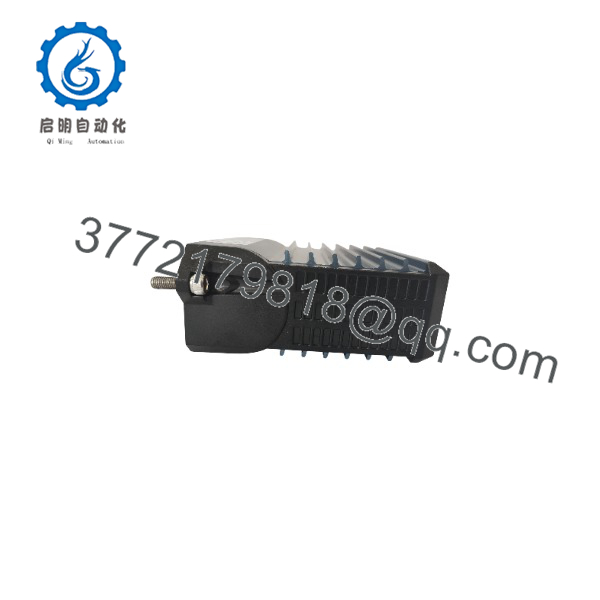
FCM2F2 RH914YZ
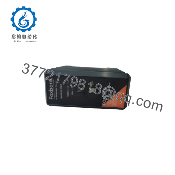
FCM2F2 RH914YZ
Installation & Configuration Guide
Stage 1: Pre-Installation (Prep & Safety)
- Verify that fieldbus redundancy is functioning on the Control Processor prior to servicing the active module.
- Put on a grounded ESD wrist strap before handling optical connectors or touching the module.
- Clean all optical fiber ST connectors using lint-free optic swabs and isopropyl alcohol before insertion.
- Confirm baseplate slot keying pins correspond to the physical keying position required for FCM-series modules.
Stage 2: Removal
- Unfasten the top and bottom captive retaining screws on the existing FCM2F2 module.
- Carefully disconnect the ST fiber optic transmit (Tx) and receive (Rx) cables, marking them clearly for proper pair identification.
- Pivot the module release latches outward to disengage the backplane interface.
- Slide the module straight out of the baseplate guide rails to avoid bending backplane pins.
Stage 3: Installation (Clone & Seat)
- Set the DIP switches on the new FCM2F2 RH914YZ to match the fiber link topology and node configuration of the removed unit.
- Align the module card edges with the baseplate slot rails and push firmly until the rear connector fully seats.
- Tighten the captive mounting screws to 0.5 Nm (4.4 in-lb) to ensure proper protective earth grounding.
- Remove protective dust caps and reconnect the ST fiber optic pairs (Tx to Rx, Rx to Tx).
Stage 4: Power-On & Testing
- Re-apply 24 V DC system power to the baseplate assembly.
- Inspect the front-panel status LED indicators:
- Solid Green: Power OK, self-test passed, and 2 Mbps Fieldbus communication established.
- Fiber Rx LED Green: Optical link signal strength is within normal operating thresholds.
- Flashing Red / Off: Optical signal loss, reversed fiber pair, or hardware failure.
- Verify remote baseplate I/O module status flags in the Foxboro System Definition Utility (SDU) to confirm complete signal propagation.
Firmware/Software Versions & Upgrade Notes
- Recommended Firmware Version: Revision 2.00 or higher for I/A Series software releases v8.x through EcoStruxure DCS v9.4.
- Backward Compatibility: Fully backward compatible with legacy FCM2F2 (P0914YZ) hardware and standard 200 Series baseplates (P0926AE/AF).
- Firmware Upgrade Risks: Do not attempt online firmware flashing or baud-rate configuration changes during live operation. Disrupting the fieldbus coupler breaks communication between the Control Processor and all downstream FBM I/O cards, triggering
BADpoint quality flags across all linked loops.
Frequently Asked Questions (FAQ)
What is the primary difference between part numbers RH914YZ and P0914YZ?
RH914YZ and P0914YZ refer to the exact same Foxboro FCM2F2 fiber optic fieldbus module. “P0914YZ” is the legacy part number, while “” designates the RoHS-compliant global manufacturing equivalent. Both share identical electrical, mechanical, and optical parameters and are 100% drop-in interchangeable.
How do you verify that these modules are genuine New Surplus?
All our New Surplus inventory is acquired directly from verified global surplus holds, project cancellations, and spare reserves. Modules arrive in original factory anti-static packaging, displaying pristine gold backplane connector contacts, unscratched optical ST ports, and verifiable OEM serial tags.
Can I hot-swap the module while the DCS is powered and operating?
Yes. The 200 Series baseplate architecture supports hot-swapping the module. If configured in a redundant dual-FCM topology, pulling one module causes the Control Processor to seamlessly switch communication traffic to the secondary module without interrupting plant processes.
What optical fiber specifications are required for the ?
The uses standard 62.5/125 µm multi-mode fiber optic cabling terminated with ST connectors operating at an 850 nm wavelength. It supports link distances of up to 2,000 meters (2 km) between baseplate locations.
What warranty coverage is included with this New Surplus module?
We support every New Surplus Foxboro module with a full 1-year functional replacement warranty. If the module experiences optical transceiver degradation, power supply faults, or fieldbus sync failures within 12 months, we replace it directly from our ready stock.



