
 WhatsApp: +86 16626708626
 Email:
  Phone: +86 16626708626
Description
Key Technical Specifications
| Parameter | Value |
|---|---|
| Manufacturer | Foxboro (Invensys / Schneider Electric) |
| Model | FEM100 |
| Product Type | Fieldbus Expansion Module |
| System Platform | Foxboro I/A Series DCS |
| Primary Controller Compatibility | FCP270 Field Control Processor |
| Fieldbus Ports | 4 Expanded Fieldbus ports |
| Communication Protocol | 2 Mbps HDLC Module Fieldbus |
| Supported FBM Capacity | Up to 32 FBMs per expanded fieldbus |
| Maximum FBM Capacity | Up to 128 FBMs per FCP270 configuration |
| Mounting Method | DIN rail mounted expansion baseplate |
| Redundancy | Supported with dual FEM100 configuration |
| Power Supply | 21 to 30 V DC nominal system supply |
| Communication Medium | Foxboro 200 Series Fieldbus |
| Operating Environment | ISA S71.04 Class G3 compatible applications |
| Application | Remote I/O expansion for process control systems |
Product Introduction
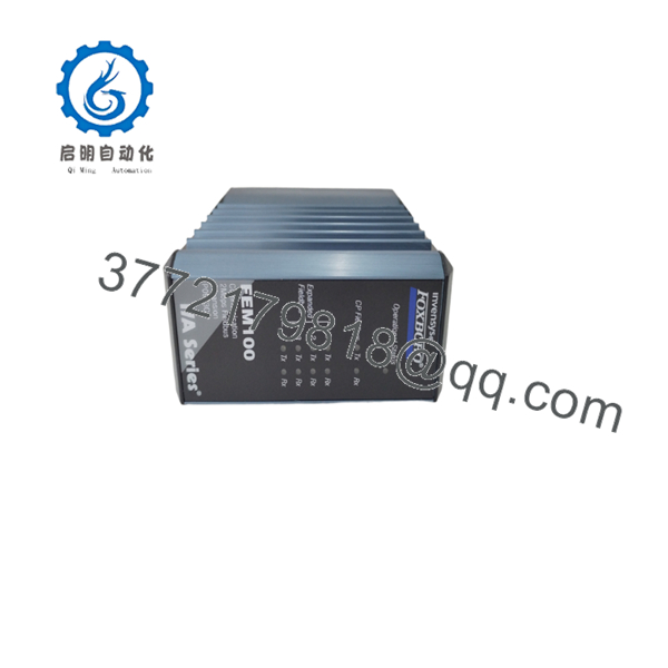
The Foxboro FEM100 is a Fieldbus Expansion Module designed for Foxboro I/A Series systems using the FCP270 Field Control Processor. It adds four expanded fieldbus channels, allowing the controller to communicate with additional 200 Series Fieldbus Modules (FBMs) distributed throughout a plant.
The FEM100 is installed on dedicated expansion baseplates and supports redundant configurations for applications requiring continued fieldbus communication during a module fault. It is commonly maintained in legacy process plants where I/A Series DCS hardware remains in service.

- FEM100
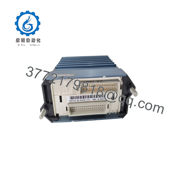
- FEM100
Installation & Configuration Guide
Stage 1: Pre-Installation Preparation (Estimated Time: 15 minutes)
⚠️ Safety First
Before replacing a :
- Notify operations about planned controller maintenance.
- Confirm affected process loops and remote FBMs.
- Verify whether the system uses redundant modules.
- Apply lockout/tagout procedures if cabinet power removal is required.
- Confirm 24 V DC supply status before handling hardware.
Tools Required
- ESD wrist strap
- Digital multimeter
- PH1 screwdriver
- Fiber/copper communication inspection tools (depending on installation)
- Smartphone for wiring and configuration photos
Data Backup
Record:
- slot location.
- Expansion baseplate type.
- Fieldbus port assignments.
- Connected FBM modules.
- Redundancy configuration.
- Current diagnostic LED status.
⚠️ Important:
The is not a standalone controller. Verify the FCP270 configuration before replacement.
Stage 2: Removing the Existing Module (Estimated Time: 10 minutes)
- Open the Foxboro I/A Series cabinet.
- Identify the expansion module.
- Record front-panel LED conditions.
- Disconnect communication connections if required.
- Release the module locking mechanism.
- Remove the from the expansion baseplate.
Inspect:
- Backplane contacts
- Connector pins
- Baseplate condition
- Dust or corrosion
⚠️ Keep the removed module available until communication testing is complete.
Stage 3: Installing the Replacement (Estimated Time: 15 minutes)
- Confirm replacement model:
- Verify:
- Correct expansion module type
- Compatible baseplate
- Correct redundancy arrangement
- Install the module into the expansion baseplate.
- Ensure proper seating.
- Restore fieldbus connections.
Configuration Checklist
☐ model confirmed
☐ Correct expansion slot installed
☐ Fieldbus connections verified
☐ Redundant partner checked
☐ 24 V DC supply confirmed
Stage 4: Power-On & Testing (Estimated Time: 20 minutes)
- Restore system power.
- Observe status LEDs.
- Verify communication with FCP270.
- Confirm all expanded fieldbus channels return online.
- Check connected FBM module status.
Recommended verification:
- FCP270 recognizes .
- All fieldbus segments communicate.
- No FBM communication alarms remain.
- Remote I/O updates correctly.
⚠️ Troubleshooting Note
If FBMs do not appear online:
- Check power supply.
- Verify fieldbus cable connections.
- Confirm the correct expansion baseplate.
- Check software compatibility.
The requires support and is not intended for use with newer controllers such as FCP280.
Frequently Asked Questions (FAQ)
Q1: What is the Foxboro used for?
The expands the number of 200 Series Fieldbus Modules that an controller can communicate with. Each provides four expanded fieldbus ports, with each port supporting up to 32 FBMs.
Q2: How many FBMs can one support?
The itself provides four fieldbus channels. Each channel can support up to 32 FBMs, allowing a total capacity of up to 128 FBMs when configured with an system.
Q3: Is compatible with ?
Yes. The was specifically designed for the Foxboro I/A Series Field Control Processor. Verify system software revision before installation.
Q4: Can be used with FCP280?
No. is intended for -based architectures. Newer controller platforms require different expansion hardware.
Q5: Does support redundancy?
Yes. A pair of modules can provide redundant expanded fieldbus operation. If one fails, the system can transfer communication through the available module when configured correctly.
Q6: Is Foxboro obsolete?
belongs to the Foxboro I/A Series legacy hardware family. Many process facilities continue using these systems, so replacement units are typically sourced from industrial automation spare inventories.
Q7: What should I check before purchasing a ?
Confirm:
- Existing controller:
- Module:
- Expansion baseplate type
- Required number of FBM channels
- Redundancy requirements
- Hardware condition and warranty
A replacement that does not match the architecture can result in fieldbus communication failures.



