
 WhatsApp: +86 16626708626
 Email:
  Phone: +86 16626708626
Description
Key Technical Specifications
| Parameter | Specification |
|---|---|
| Model | IDP10-A22A01F-M1 |
| Manufacturer | Foxboro / Invensys |
| Series | IDP10 |
| Measurement Type | Differential pressure |
| Output Signal | 4–20 mA |
| Calibrated Range | 0.5–30 inH₂O |
| Metric Range | 1.2–75 mbar / 0.12–7.5 kPa |
| Process Cover Material | 316 stainless steel |
| Sensor Material | 316L stainless steel |
| Fill Fluid | Silicone |
| Process Connection | 1/4 NPT tapped |
| Conduit Connection | 1/2 NPT |
| Product Category | Pressure transmitter |
| Lifecycle Status | Discontinued |
| Approx. Listed Weight | 11 lb |
The exact model listing identifies the IDP10-A22A01F-M1 as a pressure transmitter with a 4–20 mA output, 316 stainless-steel process cover, 316L stainless-steel sensor, silicone fill fluid, and a 0.5–30 inH₂O calibrated range.
Important: Publicly indexed documentation for this exact suffix is limited. The specifications above are tied specifically to the A22A01F-M1 listing rather than being inferred from another IDP10 variant. Confirm the nameplate and OEM documentation before substituting a different IDP10 configuration.
Product Introduction
The Foxboro IDP10-A22A01F-M1 is an IDP10-series differential pressure transmitter designed to measure low differential pressure and provide a standard 4–20 mA process signal. The documented configuration uses a 316L stainless-steel sensor, 316 stainless-steel process cover, silicone fill fluid, and 1/4 NPT process connections.
Its 0.5–30 inH₂O calibrated range makes the configuration applicable to low-pressure differential measurement rather than general high-pressure service. Because this exact model is listed as discontinued, matching the complete model code is important when replacing an installed transmitter.
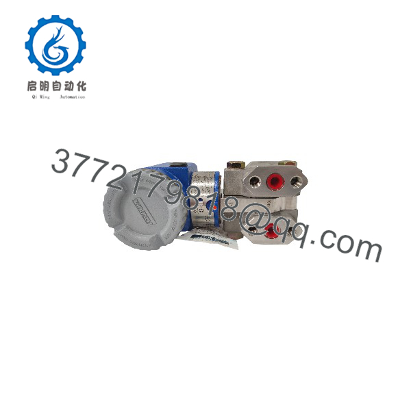
IDP10-A22A01F-M1
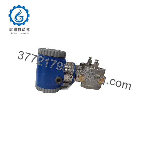
IDP10-A22A01F-M1
Installation & Configuration Guide
Stage 1 — Pre-Installation Preparation
- Record the existing transmitter’s complete model code, including IDP10-A22A01F-M1 and any nameplate suffixes.
- Verify the required differential-pressure range against the existing instrument loop.
- Confirm the process connection is compatible with the existing impulse piping.
- Verify the receiving control system expects a 4–20 mA transmitter signal.
- Isolate the process and depressurize the impulse lines before disconnecting the transmitter.
- Back up or document the existing loop configuration and calibration settings.
⚠️ Estimated time: 20–40 minutes, depending on process isolation requirements.
Stage 2 — Removing the Existing Transmitter
- Isolate both high- and low-pressure process connections.
- Vent and drain the impulse lines according to the plant procedure.
- Confirm the transmitter is electrically de-energized before opening the wiring compartment.
- Label the signal conductors before disconnecting them.
- Disconnect the process tubing and electrical connections.
- Remove the existing transmitter without contaminating the impulse connections.
⚠️ Never open a pressurized process connection simply to replace the transmitter.
Stage 3 — Installing the -A22A01F-M1
- Verify that the replacement nameplate exactly matches IDP10-A22A01F-M1.
- Inspect the 1/4 NPT process connection and mating fittings for thread damage or contamination.
- Install the transmitter using the approved sealing method for the process connection.
- Do not use the transmitter housing or electronics enclosure as a pipe wrench.
- Connect the high- and low-pressure impulse lines to their correct ports.
- Reconnect the 4–20 mA loop wiring according to the applicable Foxboro wiring documentation.
- Check conduit sealing and cable entry before energizing the loop.
⚠️ The transmitter’s pressure range and process-connection configuration must match the original installation. Do not substitute another suffix solely because the transmitter looks physically similar.
Stage 4 — Power-On & Testing
- Restore process isolation gradually.
- Energize the 4–20 mA loop.
- Check for abnormal current before placing the loop back into automatic control.
- Confirm the differential-pressure reading at a known process condition.
- Compare the transmitter output with the DCS/PLC indication.
- Check zero stability with the appropriate equalized process condition.
- Verify that the transmitter responds correctly when differential pressure changes.
- Inspect all process connections for leakage.
- Record the installed model, calibration range, loop reading, and commissioning results.
⚠️ Estimated time: 30–60 minutes after the process is safely isolated and restored.
FAQ
What type of inent is the ?
It is a Foxboro -series differential pressure transmitter with a documented 4–20 mA output.
What is the calibrated range?
The exact model listing specifies 0.5–30 inH₂O, equivalent to approximately 1.2–75 mbar or 0.12–7.5 kPa.
What materials are used in this configuration?
The documented configuration uses a 316 stainless-steel process cover, 316L stainless-steel sensor, and silicone fill fluid.
What process connection does it use?
The exact listing specifies a 1/4 NPT tapped process connection and a 1/2 NPT conduit connection. Verify the installed piping and transmitter nameplate before replacement.
Is the still manufactured?
The exact model is listed as discontinued by the manufacturer. Current replacement inventory therefore needs to be checked by exact part number and condition.
Can another transmitter be used as a direct replacement?
Not automatically. model suffixes encode configuration differences. The replacement should match the measurement range, process connection, materials, output configuration, and other nameplate options before installation.
What should I verify when buying a replacement?
Verify the complete model code, nameplate data, calibration range, process connection, physical condition, and test status. Current secondary-market listings show this exact part in multiple conditions, including never-used original packaging and refurbished units, so condition should be confirmed before purchase.



