WhatsApp: +86 16626708626
 Email:
 Phone: +86 16626708626
Description
Key Technical Specifications
⚠️ Verification notice: Several aftermarket listings incorrectly describe the P0500RU as a power supply, communication module, analog output module, or control module. The most consistent distributor record identifies it as a Foxboro/Invensys FBM termination cable, associated with FBM 3-33AMP, and discontinued by the manufacturer. Confirm the physical cable, connector ends, and length against the installed Foxboro I/A cabinet before ordering.
| Parameter | Value |
|---|---|
| Catalog number | P0500RU |
| Brand | Foxboro / Invensys |
| Product type | Termination cable / cable assembly |
| Associated equipment | Foxboro I/A Series FBM hardware |
| Associated marking | FBM 3-33AMP |
| Primary function | Provides FBM fieldbus termination and cable interconnection |
| Manufacturer status | Discontinued by manufacturer |
| Reported shipping weight | 0.33 kg |
| Connector configuration | Verify exact connector ends and cable length from the installed assembly |
| Compatible system | Foxboro I/A Series distributed control system |
| Typical use | FBM cabinet termination, fieldbus interconnection, and legacy I/A system maintenance |
| Condition note | Cable assemblies should be inspected for connector damage, conductor continuity, shield integrity, and insulation condition |
| Replacement scope | Cable assembly only; FBM modules, carriers, and power supplies are separate items |
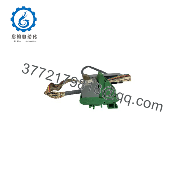
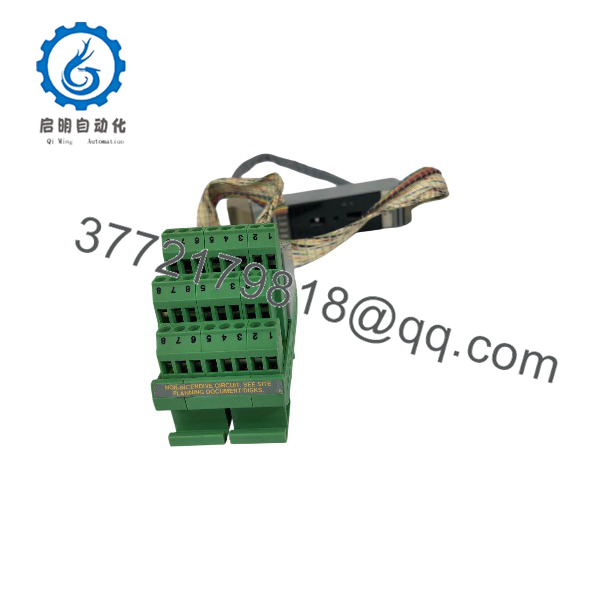
The P0500RU is a discontinued Foxboro/Invensys cable assembly, not an electronic I/O or power module. Distributor records classify it as cable/wire and identify its function as an FBM termination cable for the Foxboro I/A Series.
Product Introduction
The Foxboro P0500RU is a termination cable assembly for Foxboro I/A Series FBM installations. It is used to terminate or interconnect FBM-related cabling in a legacy Foxboro DCS cabinet, helping maintain the original fieldbus and I/O-carrier wiring arrangement.
This part is selected when maintaining an existing Foxboro I/A system without altering cabinet wiring or replacing functioning FBM hardware. Because it is discontinued, buyers should verify connector types, cable length, shield termination, and revision compatibility before ordering.
P0500RU
P0500RU
Installation & Configuration Guide
Stage 1: Pre-Installation Preparation
Estimated time: 15–30 minutes.
- ⚠️ Notify operations and obtain authorization for work on the Foxboro I/A control network.
- Identify the affected FBM carrier, node, and cable route.
- Apply lockout/tagout where required for cabinet work; do not disconnect active fieldbus cables without an approved outage plan.
- Prepare an ESD wrist strap, cable labels, multimeter or cable tester, small screwdrivers, and a camera.
- Photograph the existing P0500RU routing, connector orientation, shield-ground termination, and FBM carrier position.
- Record the cable length, connector types, and any printed revision or date code.
⚠️ Do not assume all Foxboro FBM termination cables are interchangeable. Connector gender, cable length, shielding, and termination method must match the installed layout.
Stage 2: Removing the Old Cable
Estimated time: 10–20 minutes.
- Confirm the affected FBM carrier is safe to isolate or that the replacement can be installed under the site’s approved online-maintenance procedure.
- Label both ends of the existing P0500RU cable and its associated FBM/carrier positions.
- Disconnect the cable connectors by their connector bodies; do not pull on the cable jacket.
- Release any cable clamps, ties, or strain reliefs.
- Remove the old cable while preserving its routing path.
- Inspect the FBM connectors, carrier connectors, and cable-entry hardware for bent pins, contamination, or damaged shielding.
⚠️ Keep the old P0500RU until the replacement cable has passed continuity, shield, and communication checks.
Stage 3: Installing the New Cable
Estimated time: 10–15 minutes.
- Verify the replacement is a Foxboro FBM termination cable and that its connectors match the original assembly.
- Put on an ESD wrist strap before touching FBM connectors.
- Route the cable along the original path, maintaining separation from AC power and high-energy wiring.
- Connect each end fully and verify that locking hardware or retention clips engage.
- Reinstall cable clamps and strain relief without over-compressing the jacket.
- Restore the shield-ground termination exactly as found in the original installation.
Self-checklist:
- Correct P0500RU cable and connector configuration confirmed
- Cable length and routing match the original
- Both connectors fully seated and secured
- Shield termination restored
- Cable strain relief installed
- FBM carrier and node identification recorded
Stage 4: Power-On & Testing
Estimated time: 15–30 minutes.
- ⚠️ Before restoring service, perform a continuity and shield-integrity check with the cable disconnected from active electronics where practical.
- Restore the FBM carrier and communication path according to the approved Foxboro I/A procedure.
- Observe FBM and communication status indicators.
- Confirm that the control system recognizes the affected FBM and that no communication fault is present.
- Verify live process values, output commands, and diagnostic status for the affected FBM.
- Monitor the communication path through at least one complete control-cycle period before closing the work order.
⚠️ If communication errors persist after replacement, check connector seating, cable shielding, ground bonding, FBM address/configuration, and the upstream communication module before condemning the new cable.
Frequently Asked Questions (FAQ)
Is the Foxboro P0500RU a power supply or communication module?
No. Reliable distributor records identify it as a discontinued Foxboro/Invensys FBM termination cable, associated with FBM 3-33AMP. Some aftermarket pages mislabel it as a power supply, fieldbus module, or analog output module; do not order based on those descriptions alone.
Is the P0500RU obsolete?
Yes. It is listed as discontinued by the manufacturer, so availability depends on remaining surplus, refurbished, or exchange stock.
Can I use a generic cable instead?
Only if the replacement matches connector type, pinout, conductor count, shielding, length, and termination method. For a Foxboro I/A FBM installation, an incorrect generic cable can introduce communication faults or ground-loop problems.
Will replacing the cable erase FBM configuration?
No. FBM identity and configuration reside in the Foxboro I/A control system and FBM hardware, not in the cable. Still, record the affected node, carrier, and FBM positions before disconnecting anything.
Can I hot-swap the P0500RU?
Do not assume so. Cable replacement may be possible during controlled maintenance, but it depends on the FBM carrier, redundancy arrangement, and site procedure. Follow the approved Foxboro I/A maintenance method.
What should I inspect on a used P0500RU?
Check connector pins, insulation, jacket abrasion, shield continuity, bend damage, and secure termination. A cable can look cosmetically acceptable but still cause intermittent communication faults.
Why is the price lower than original OEM pricing?
Because the P0500RU is discontinued legacy inventory. Pricing reflects availability, condition, testing, warranty exposure, and the difficulty of sourcing a cable with the correct Foxboro I/A connector configuration.