 WhatsApp: +86 16626708626
 Email:
 Phone: +86 16626708626
Description
Key Technical Specifications
| Parameter | Value |
|---|---|
| Catalog number | P0926GH |
| Brand | Foxboro / Invensys |
| System platform | Foxboro I/A Series |
| Product type | External termination assembly (ETA) / terminal board |
| Associated communication FBMs | FBM224 Modbus communication interface; FBM230 Field Device System Integrator; FBM231 communication module |
| Termination style | Compression screw |
| Construction | Polyamide |
| Terminal arrangement | Three tiers of eight-position terminal blocks for RS-422/RS-485 connections |
| Supported serial interfaces | RS-232, RS-422, RS-485, depending on the paired FBM |
| Primary function | Provides field-side wiring termination and serial-communication connection for the paired FBM |
| Related cable/reference | P0926GL-0C compression polyamide termination assembly |
| Installation | DIN-rail or panel-mounted termination arrangement, depending on system configuration |
| Physical reference | Approximately 12.0 × 6.0 × 5.0 cm; approximately 0.2 kg |
| Compatibility caution | P0926GH is the termination assembly, not the FBM communication module itself |
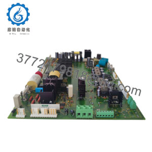
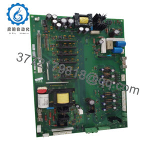
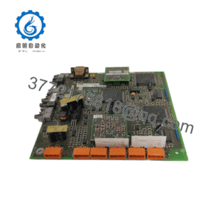
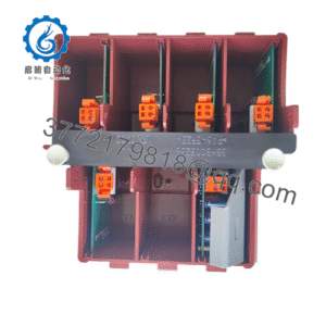
The P0926GH is a compression-screw, polyamide termination assembly associated with Foxboro FBM224, FBM230, and FBM231 communication modules. It provides the field-side serial-communication wiring interface; the active communication electronics reside in the paired FBM.
Product Introduction
The Foxboro P0926GH is an I/A Series compression termination assembly used with FBM224, FBM230, and FBM231 communication modules. It provides the terminal interface for serial field-device communication, including RS-232, RS-422, and RS-485 connections depending on the installed FBM type.
This assembly is selected when maintaining an existing Foxboro I/A communication loop without changing the FBM, communication protocol, or field-device wiring architecture. Because it is a passive termination assembly, buyers should verify the paired FBM model, serial standard, connector arrangement, and cable routing before ordering.
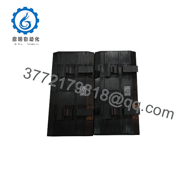
P0926GH
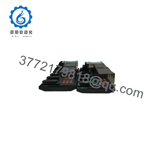
P0926GH
Installation & Configuration Guide
Stage 1: Pre-Installation Preparation
Estimated time: 20–30 minutes.
- ⚠️ Obtain an outage or approved online-maintenance authorization for the affected Foxboro I/A communication loop.
- Identify the paired FBM—FBM224, FBM230, or FBM231—and record its slot, node, and communication configuration.
- Apply lockout/tagout where required; do not disconnect an active serial communication cable without an approved maintenance procedure.
- Prepare an ESD wrist strap, insulated screwdrivers, multimeter or serial-loop tester, wire labels, ferrules, and a camera.
- Photograph the existing P0926GH terminal numbering, shield-ground termination, cable routing, and FBM/baseplate position.
- Record the communication protocol, baud rate, node addresses, termination-resistor settings, and cable shield arrangement.
- Verify that the replacement is P0926GH, not P0926GL-0C or another Foxboro termination assembly.
⚠️ The P0926GH is passive field-wiring hardware. Communication faults are often caused by the paired FBM, protocol configuration, cable shield, or termination resistor—not the terminal assembly alone.
Stage 2: Removing the Old Termination Assembly
Estimated time: 15–25 minutes.
- Disable or safely isolate the affected communication loop according to the site procedure.
- Label every serial conductor, shield, earth reference, and FBM-side cable at both ends.
- Disconnect field-device cables and the FBM-side communication cable by their connector bodies; do not pull on conductors.
- Release the P0926GH mounting hardware or DIN-rail clip.
- Remove the termination assembly while preserving its orientation and cable routing.
- Inspect the FBM connector area, baseplate, terminal housings, and cable shields for damage, contamination, or loose terminations.
⚠️ Keep the removed P0926GH until the replacement has passed continuity, shield-integrity, and communication checks.
Stage 3: Installing the New Termination Assembly
Estimated time: 15–25 minutes.
- Verify the replacement is Foxboro P0926GH, a compression polyamide termination assembly for FBM224/230/231.
- Put on an ESD wrist strap before handling FBM connectors or communication wiring.
- Mount the P0926GH in the same location and orientation as the original.
- Reconnect labeled RS-232, RS-422, or RS-485 conductors, shields, and earth references.
- Torque compression terminals to the specified value; confirm that no stray strands protrude.
- Restore the cable shield and shield-ground termination exactly as found in the original installation.
- Reconnect the FBM-side cable and verify that the FBM and termination assembly are fully seated.
Self-checklist:
- Correct P0926GH compression polyamide assembly confirmed
- Paired FBM224/230/231 compatibility confirmed
- Serial protocol and wiring standard verified
- Shield and earth terminations restored
- Compression terminals torqued and inspected
- FBM-side cable fully seated
- Communication addresses and termination settings recorded
Stage 4: Power-On & Testing
Estimated time: 30–60 minutes.
- ⚠️ Before restoring communication, check conductor continuity, shield continuity, insulation to earth, and correct RS-422/RS-485 polarity.
- Restore the FBM and communication-loop power according to the approved startup sequence.
- Confirm FBM status, fieldbus A/B communication status, and module health.
- Verify serial communication parameters: protocol, baud rate, parity, stop bits, node address, and termination-resistor setting.
- Test communication to each connected field device or downstream serial network.
- Confirm that the FBM reports no communication fault and that live process data updates correctly.
- Monitor the communication loop through at least one complete control-cycle period before returning it to service.
⚠️ If communication fails, check cable polarity, shield grounding, termination resistors, baud rate, FBM configuration, and field-device response before replacing the P0926GH.
Frequently Asked Questions (FAQ)
Is the Foxboro P0926GH an FBM module?
No. It is a termination assembly for FBM224, FBM230, or FBM231 communication modules. The active communication electronics reside in the paired FBM, not in the P0926GH.
Which FBMs work with P0926GH?
It is associated with FBM224, FBM230, and FBM231. Confirm the exact FBM model and serial-communication standard before ordering.
Does P0926GH support RS-485?
Yes, when paired with a compatible FBM and configured for RS-485 communication. The assembly provides three tiers of eight-position terminal blocks for RS-422/RS-485 wiring.
Can I use P0926GL-0C instead?
Do not substitute automatically. P0926GL-0C is a related compression polyamide termination assembly, but the exact FBM pairing, connector arrangement, and wiring standard must be verified first.
Can I hot-swap the P0926GH?
Do not assume so. The termination assembly is passive, but disconnecting it can interrupt an active serial communication loop. Follow the approved Foxboro I/A maintenance procedure for the paired FBM.
What should I inspect on a used P0926GH?
Check compression terminals, conductor damage, cracked polyamide housing, FBM connector pins, shield terminations, and signs of overheating. A used assembly should have documented continuity and insulation checks.
Why does the P0926GH cost more than a generic terminal block?
It is a Foxboro-engineered I/A Series termination assembly with defined FBM compatibility, serial-communication terminal arrangement, and system-specific mechanical/electrical interfaces—not a generic terminal block.