
 WhatsApp: +86 16626708626
 Email:
  Phone: +86 16626708626
Description
Key Technical Specifications
The EP-3959G-C1 is identified in current secondary-market listings as a Fuji inverter power driver board. A supplier listing specifically associates EP-3959G-C1 with the Fuji Inverter Power Driver Board family and with EP-3959G-C2/C3 variants.
- Manufacturer: Fuji Electric
- Model: EP-3959G-C1
- Board Type: Inverter power driver board
- Application Family: Fuji G11/P11 series
- Board Family: EP-3959G
- Primary Function: Drive/control circuitry within the inverter power section
- Related Revision/Variant: EP-3959G-C2
- Related Variant: EP-3959G-C3
- Mounting: Internal inverter PCB assembly
- Installation: Cabinet-mounted inverter equipment
- Lifecycle Status: Legacy / replacement-market component
- Condition Options: New, New Surplus, Used/Tested, depending on supplier
⚠️ Specification limitation: Publicly indexed sources do not provide a reliable manufacturer datasheet for EP-3959G-C1 with confirmed electrical ratings, connector pinout, dimensions, weight, gate-drive voltage, or supported inverter horsepower. Do not substitute specifications from EP-3959C1, EP-3959E-C1, or EP-3959G-C3 simply because the numbers look similar.
A separate Fuji equipment reference identifies EP-3959G-C3 specifically as a discontinued PCB driver board for G11/P11 equipment. That supports the G11/P11 family association but does not establish that EP-3959G-C1 and C3 are electrically interchangeable.
Product Introduction
The Fuji Electric EP-3959G-C1 is an inverter power driver board used within Fuji G11/P11-series drive equipment. Current parts listings identify it as a power driver board, while related EP-3959G variants are associated with the same inverter board family.
This is a maintenance-level replacement component, not a standalone PLC or general-purpose control module. For a replacement, the critical checks are the exact board suffix, connector arrangement, revision markings, installed inverter model, and gate/power-stage configuration.
Installation & Configuration Guide
Estimated physical replacement: 20–30 minutes for an experienced drive technician.
Commissioning: Additional time is required for DC-bus checks, gate-drive verification, motor testing, and inverter parameter validation.
Stage 1: Pre-Installation Preparation — 10 minutes
- ⚠️ Stop the inverter and isolate the drive from incoming power.
- Apply the site’s lockout/tagout (LOTO) procedure.
- Wait for the DC bus to discharge according to the Fuji drive service procedure.
- Measure the DC bus with a properly rated multimeter. Do not rely on the charge/discharge indicator alone.
- Prepare:
- ESD wrist strap
- Digital multimeter
- Insulated screwdrivers
- Wire/connector labels
- Camera or smartphone
- Record the complete inverter model and rating.
- Photograph the existing EP-3959G-C1 from multiple angles.
- Record:
- PCB revision
- Serial/traceability markings
- Connector positions
- Jumper or switch settings
- Cable routing
- Save the inverter parameter set before removing the board whenever the drive’s control system permits it.
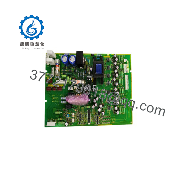
EP-3959G-C1
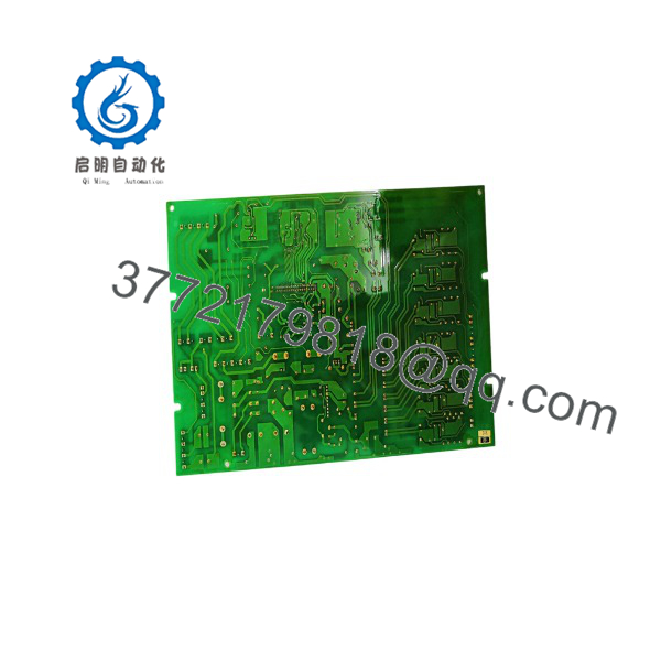
EP-3959G-C1
Stage 2: Removing the Old Board — 5–10 minutes
- Confirm that the DC bus is at the safe voltage specified by the applicable Fuji service documentation.
- Remove the inverter enclosure covers.
- Photograph every connector before disconnecting it.
- Label connectors that could physically be interchanged.
- Disconnect ribbon cables, signal connectors, and control wiring without pulling on the conductors.
- Remove the board retaining hardware.
- Lift the PCB carefully and avoid contact with exposed power electronics.
- Inspect the surrounding drive assembly for:
- Burn marks
- Cracked solder joints
- Discolored connectors
- Loose terminals
- Electrolytic capacitor leakage
- Contamination
- ⚠️ Keep the original EP-3959G-C1 until the replacement has passed functional testing.
Stage 3: Installing the New EP-3959G-C1 — 5–10 minutes
- Use ESD protection before handling the replacement PCB.
- Compare the replacement against the removed board:
- EP-3959G-C1 marking
- Connector locations
- PCB layout
- Revision information
- Mounting-hole positions
- Do not assume EP-3959G-C2 or EP-3959G-C3 is a direct electrical substitute.
- Install the PCB in the original mounting position.
- Reconnect each connector according to the photographs and approved wiring documentation.
- Verify that connectors are fully seated.
- Check for trapped cables or wiring contacting heat sinks and power terminals.
- Reinstall all retaining hardware.
- Perform a visual inspection before restoring power.
Replacement checklist:
- Exact EP-3959G-C1 suffix confirmed
- PCB revision recorded
- Connector positions verified
- All connectors seated
- No loose hardware
- No wiring trapped under PCB
- DC-bus safety check completed
- ESD precautions maintained
Stage 4: Power-On & Testing — 10+ minutes
- Keep the motor/load in a controlled condition during initial testing.
- Energize the drive according to the applicable Fuji startup procedure.
- Check the drive’s display/status indicators for immediate fault codes.
- Verify the control supply and DC-bus behavior.
- Check that the drive recognizes the installed control electronics.
- Restore or verify the saved inverter parameters.
- Confirm motor nameplate data and command-source settings.
- Check acceleration/deceleration parameters before issuing a RUN command.
- Perform a controlled low-speed test.
- Monitor:
- Output current
- DC-bus voltage
- Motor rotation
- Drive fault status
- Abnormal noise or heating
- Increase operating speed/load gradually.
- Record the final drive parameters and replacement-board identification in the maintenance record.
⚠️ Critical warning: A power driver board is part of the drive’s power-control chain. A board that powers up without an immediate alarm is not automatically proven good. Gate-drive faults, feedback problems, insulation issues, or incorrect board matching can appear only when the inverter is commanded to operate.
Frequently Asked Questions (FAQ)
Is the Fuji EP-3959G-C1 a PLC module?
No. Available listings identify the EP-3959G-C1 as a Fuji inverter power driver board, not a PLC CPU or I/O module.
Which inverter does EP-3959G-C1 belong to?
The available evidence associates the EP-3959G family with Fuji G11/P11 inverter equipment. EP-3959G-C3 is explicitly listed as a G11/P11 driver board, while EP-3959G-C1 is listed in the same EP-3959G family.
Is EP-3959G-C1 interchangeable with EP-3959G-C3?
Do not assume it is. The C1 and C3 suffixes indicate different board variants. Although both appear in the same family, I found no reliable source establishing electrical or functional interchangeability. Match the exact board suffix and the inverter’s original hardware configuration.
Is EP-3959G-C1 obsolete?
The component appears to be a legacy/secondary-market part. Fuji equipment references identify the related EP-3959G-C3 as discontinued by the manufacturer.
That does not by itself prove that every EP-3959G-C1 revision has the same formal discontinuation status, so procurement should be based on actual stock condition and traceability.
Can I replace the board without saving inverter parameters?
I would not. The board replacement itself may not be where the inverter’s complete parameter set resides, but a maintenance team should still save the drive configuration before opening the unit. That gives you a known recovery point if the replacement exposes a parameter, feedback, or compatibility problem.
Why do suppliers describe EP-3959G-C1 as “power driver board” but provide very different specifications?
Because most current information appears to come from secondary-market listings rather than a complete current OEM datasheet. One current listing identifies EP-3959G-C1 as a Fuji inverter power driver board, while other Fuji equipment references provide application information for related EP-3959G variants.
For procurement, the exact suffix and physical-board comparison matter more than a generic horsepower or voltage claim copied from another EP-3959 variant.
What should I provide when requesting a replacement quote?
Provide the supplier with:
- EP-3959G-C1
- Complete Fuji inverter model
- Inverter input/output rating
- Photographs of the original PCB
- PCB revision and serial markings
- Connector photographs
- Existing drive fault code, if applicable
- Required condition: New Original, New Surplus, or Refurbished/Tested
This is particularly important because current listings show EP-3959G-C1, C2, and C3 as separate purchasable variants rather than treating them as one universal board.



