
 WhatsApp: +86 16626708626
 Email:
  Phone: +86 16626708626
Description
3. Key Technical Specifications
| Parameter | Specification |
| Manufacturer | Mitsubishi Electric |
| Model Code | FX0N-16EX / FX0N-16EX-ES/UL |
| Input Points | 16 points |
| Input Signal Voltage | 24 V DC (+10% / -10%) |
| Input Current | 5 mA @ 24 V DC |
| Input Circuit Isolation | Photocoupler / Optocoupler insulation |
| Input Response Time | ~10 ms |
| Internal Power Draw | 50 mA @ 5 V DC (supplied from main base unit backplane bus) |
| Connection Type | European-style removable screw terminal block |
| Dimensions (W x H x D) | 70 mm x 90 mm x 87 mm (2.76″ x 3.54″ x 3.43″) |
| Weight | 0.30 kg (0.66 lbs) |
4. Product Introduction & Supply Chain Strategy
The Mitsubishi FX0N-16EX is a 16-point 24V DC digital input expansion block designed to expand sensor, switch, and push-button monitoring on legacy MELSEC-F series PLC architectures (including FX0N, FX1N, FX2N, and FX3U base units). Maintenance teams count on this module for reliable photocoupler-isolated signal conditioning across automated processing cells and material handling systems.
Sourcing this discontinued extension block as New Surplus provides an essential replacement line against unexpected input bank failures. Installing worn second-hand or poorly stored refurbished expansion blocks risks field signal cross-talk, degraded optical isolation, and intermittent I/O dropouts. Securing a factory-sealed unit ensures zero backplane ribbon connector wear, pristine terminal screws, and long-term signal integrity without requiring costly cabinet panel redesigns.
5. Installation & Configuration Guide
Stage 1: Pre-Installation (Prep & Safety)
- Enforce Lock-Out/Tag-Out (LOTO) procedures on the main AC/DC supply feeding the target PLC chassis.
- Put on a grounded ESD wrist strap connected to a verified metal enclosure frame.
- Label and photograph all input terminal wiring leads and note the module’s exact sequence on the right-hand expansion bus.
Stage 2: Removal
- Unplug the 24V DC input terminal blocks or loosen individual terminal screws to free sensor wiring.
- Carefully unclip the flat bus ribbon cable connecting the FX0N-16EX to the adjacent main CPU or expansion block.
- Release the lower DIN-rail locking tab using a flat-head screwdriver and lift the unit straight off the mounting rail.
Stage 3: Installation (Clone & Seat)
- Snap the FX0N-16EX firmly onto the DIN rail in the same sequential order as the previous module.
- Connect the expansion ribbon cable securely into the bus socket of the preceding unit until fully seated.
- Wire the 16 input points using the photos taken in Stage 1, ensuring 24V DC sink/source common connections (
S/Sterminal) match your field sensor wiring configuration.
Stage 4: Power-On & Testing
- Re-apply main power to the base PLC unit.
- Verify that the
POWERindicator on the base CPU remains normal and noERRORLEDs illuminate. - Trigger field sensors sequentially and confirm that the corresponding input status LEDs on the front panel of the -16EX turn on bright green.
- Verify bit state transitions (
Xaddresses) on the host PLC software monitoring panel.
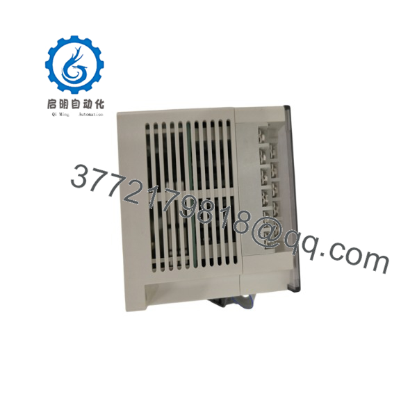
FXON-16EX
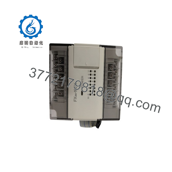
FXON-16EX
6. Firmware/Software Versions & Upgrade Notes
- Base Unit Compatibility: Native support across , FX1N, FX2N, and FX3U controllers. When connecting to FX3U main units, an FX2N-CNV-BC extension cable adapter may be required depending on base enclosure bus routing.
- Addressing Allocation: Input addresses (
Xdesignation) are assigned automatically based on physical distance from the main processing unit. Adding or removing modules upstream shifts downstream I/O address mapping—always verify element mapping in GX Developer or GX Works2 before running automated sequences. - Bus Power Limit Warning: The draws 5 V DC logic power directly from the main unit’s internal backplane bus. Calculate total 5 V DC bus current consumption across all attached expansion units to ensure the main unit’s internal power supply capacity is not exceeded.
7. Frequently Asked Questions (FAQ)
Q:this module brand new or recovered from a used control panel?
This module is 100% genuine New Surplus stock. It has never seen field duty, has never been installed in an active control panel, and is not a refurbished part. It arrives in its original factory packaging.
Q: Why choose New Surplus over cheaper refurbished input blocks?
Refurbished input blocks frequently suffer from worn bus ribbon cables, degraded optocoupler isolation chips, and stripped terminal screws due to repeated wiring. Buying verified New Surplus guarantees original OEM insulation resistance, reliable signal isolation, and zero downtime.
Q: The series is long discontinued. Can I use this on newer FX-series PLCs?
Yes. Mitsubishi designed the expansion series with forward compatibil The integrates seamlessly with FX1N, FX2N, and FX3U main units, making it an ideal drop-in spare for mixed-generation plant floors.
Q: Does this module require an external 24V DC power connection to operate its internal logic?
No. The module’s internal logic and optocouplers draw operational power (50 mA @ 5 V DC) directly through the expansion bus cable connected to the main PLC base unit. External 24 V DC is only required to drive the field input loop circuits.
Q: What warranty comes with this expansion block?
We back our Newplus modules with a full 1-year replacement warranty. If any channel fails or exhibits hardware errors during initial commissioning or normal operation, we replace it directly from our warehouse stock.



