
 WhatsApp: +86 16626708626
 Email:
  Phone: +86 16626708626
Description
3. Key Technical Specifications
| Parameter | Specification |
| Manufacturer | Mitsubishi Electric |
| Model Code | FX1N-60MR-001 / FX1N-60MR-A |
| Power Supply Voltage | 100 to 240 V AC (+10% / -15%), 50/60 Hz |
| Power Consumption | 35 W |
| Integrated Digital Inputs | 36 points (24 V DC, 7 mA sink/source) |
| Integrated Digital Outputs | 24 points (Relay, 2 A/point @ 250 V AC or 30 V DC) |
| Program Capacity | 8,000 steps EEPROM internal memory (expandable via memory cassette) |
| High-Speed Counters | 6 channels total (up to 60 kHz single phase / 30 kHz A/B phase) |
| Communication Interface | RS-422 programming port (8-pin mini-DIN) |
| Dimensions (W x H x D) | 175 mm x 90 mm x 75 mm (6.89″ x 3.54″ x 2.95″) |
| Weight | 0.80 kg (1.76 lbs) |
4. Product Introduction & Supply Chain Strategy
The Mitsubishi FX1N-60MR-001 is a compact PLC main unit engineered for small-to-medium industrial control applications, including packaging lines, material handling conveyors, and dedicated machine automation. Plant engineers depend on this controller for its high digital channel density, built-in high-speed counting capabilities, and reliable relay output switching for inductive AC/DC loads.
Because Mitsubishi has formally transitioned the FX1N line to End-of-Life (EOL) status, securing this specific unit as New Surplus provides a crucial operational buffer. Swapping a failed CPU with an unverified, worn refurbished unit risks immediate backplane faults, compromised memory retention, and worn output relay contacts. Maintaining genuine factory-sealed stock guarantees full internal relay lifespan, zero terminal screw degradation, and zero downtime while avoiding costly control panel re-engineering to newer FX3U or FX5U platforms.
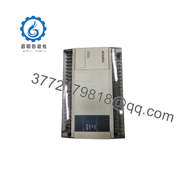
FX1N-60MR-001
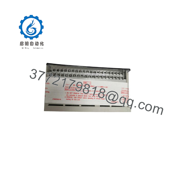
FX1N-60MR-001
5. Installation & Configuration Guide
Stage 1: Pre-Installation (Prep & Safety)
- Enforce Lock-Out/Tag-Out (LOTO) procedures on the main 100–240V AC power distribution breaker feeding the target panel.
- Put on an anti-static wrist strap anchored to a verified earth ground terminal.
- Take high-resolution photos of all terminal block wiring and record expansion module alignment sequences before pulling the old unit.
Stage 2: Removal
- Unplug the 8-pin mini-DIN programming cable and any attached BD extension boards or memory cassettes.
- Disconnect all screw-terminal blocks or loosen individual terminal screws to release input, output, and power wiring harness leads.
- Disengage the DIN-rail mounting clip at the bottom of the module housing and lift the main unit off the rail.
Stage 3: Installation (Clone & Seat)
- Mount the FX1N-60MR-001 onto the DIN rail, pressing firmly until the mounting clip locks securely into place.
- Reconnect any right-side expansion bus cables and re-seat optional top-mounted communication/analog BD boards.
- Reattach wiring strictly according to the terminal map taken in Stage 1, ensuring 24 V DC sensor power polarities and AC line connections match OEM specifications.
Stage 4: Power-On & Testing
- Verify AC line voltage measures between 100 V AC and 240 V AC before applying power.
- Move the run/stop toggle switch on the PLC front panel to the
STOPposition. - Apply power and verify the
POWERLED lights solid green without theBATT.VorERRORLEDs illuminating red. - Download the ladder logic program via GX Developer or GX Works2 and toggle the switch to
RUN. Confirm normal input/output LED activity.
6. Firmware/Software Versions & Upgrade Notes
- Software Compatibility: Fully compatible with Mitsubishi GX Developer (V7.0 and higher) and GX Works2 (V1.00 and higher).
- Memory Cassette Handling: If transferring a program via an external FX1N-EEPROM-8K cassette, always insert or remove the cassette while the PLC is completely powered off to prevent EEPROM corruption.
- Migration & Upgrade Caution: When converting ladder logic from an older -60MR-001 to a newer FX3U series replacement, review device memory maps (such as timers, counters, and auxiliary relays). Certain special data registers (
D8000series) differ across generations and require remapping before live execution.
7. Frequently Asked Questions (FAQ)
Q: Is this -60MR-001 unit brand new or pulled from an old production line?
This module is 100% genuine New Surplus stock. It has never been installed in an operational panel, never deployed on a plant floor, and is not a refurbished board. It remains in original factory packaging.
Q: Why pay a premium for New Surplus when cheaper refurbished controllers exist?
Refurbished PLC units often feature mechanically degraded internal relays, dried-out filtering capacitors, and worn terminal threads. Purchasing verified New Surplus guarantees 100% remaining relay contact life (rated for ~200,000 operations under full load) and eliminates unexpected downtime caused by internal component wear.
Q: The series is obsolete. How does having this spare help my facility?
Holding a factory-sealed -60MR-001 on-site acts as an immediate drop-in replacement policy. It prevents days or weeks of unscheduled downtime caused by sourcing rare legacy parts or spending thousands of dollars rewriting logic for newer PLC hardware formats.
Q: Can I use this relay output model to directly drive high-frequency pulse outputs?
No. The -MR model uses mechanical relay outputs, which are limited to slow switching speeds (~10 Hz maximum) to prevent premature contact burn-out. For high-speed pulse train outputs (e.g., driving stepper or servo drives), you must use a transistor output model like the -60MT.
Q: What warranty coverage comes with this module?
We back our Surplus PLC base units with a comprehensive 1-year replacement warranty. If the module exhibits any functional defects or hardware errors upon installation, we swap it directly from our warehouse inventory.



