
 WhatsApp: +86 16626708626
 Email:
  Phone: +86 16626708626
Description
3. Key Technical Specifications
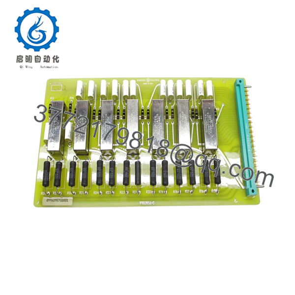
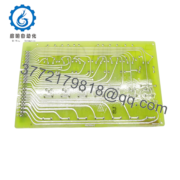
- Product Type: Circuit Board Assembly (Relay Driver)
- Functional Role: Opto-isolated relay driving for EHC systems
- System Integration: GE turbine control / EHC cabinet
- Signal Type: Digital control signals to relay outputs
- Isolation Method: Optical isolation (signal protection layer)
- Power Supply: Backplane-fed DC (system dependent)
- Connector Type: Edge connector to rack/backplane
- Application: Steam/gas turbine electro-hydraulic control
- Mounting: Slot-in PCB within control rack
- Operating Temperature: Typically 0 to 60°C (cabinet dependent)
4. Product Introduction
The GE 0996D957G0001 is an opto-isolated relay driver board used in GE electro-hydraulic control (EHC) systems for turbine applications. Its primary role is to interface low-level control signals from the controller to field relay outputs while maintaining electrical isolation.
In field installations, this board is commonly found in steam turbine governor systems and hydraulic control cabinets. Engineers typically replace it when relay outputs become unstable or isolation circuits degrade. There is no direct modern drop-in replacement—most sites maintain spare inventory to avoid forced system upgrades.
5. Installation & Configuration Guide
Stage 1: Pre-Installation Preparation (Estimated Time: 15 min)
- ⚠️ Safety First:
- Notify control room and operators.
- Bring turbine/system to safe shutdown.
- Lock out/tag out all power sources.
- Wait at least 5–10 minutes for stored energy discharge.
- Tools Required:
- ESD wrist strap
- Insulated screwdriver
- Multimeter (Fluke 115 or equivalent)
- Wire labels
- Smartphone for documentation
- Data Backup:
- Photograph board slot and wiring harness layout.
- Record relay output mapping if available.
- Document adjacent boards (critical for EHC racks).
Stage 2: Removing the Old Module (Estimated Time: 10 min)
- Open EHC cabinet and identify the board.
- Label all connectors before removal.
- Disconnect cables carefully—older headers are fragile.
- Release retaining clips.
- Pull the board straight out to avoid edge connector damage.
- ⚠️ Note:
Keep the old board available. You may need it to verify wiring or troubleshoot signal paths.
Stage 3: Installing the New Module (Estimated Time: 10–15 min)
- Apply ESD protection before handling.
- Verify exact model: 0996D957G0001 (check full suffix).
- Compare physical layout with old board (component population, connectors).
- Insert board firmly into rack slot—ensure full engagement.
- Reconnect all cables with proper seating.
- Self-Checklist:
- Correct model verified
- Board fully seated
- Connectors secured
- No bent pins
Stage 4: Power-On & Testing (Estimated Time: 15–20 min)
- Pre-Power Check:
- Measure supply voltage rails.
- Confirm no short circuits on output lines.
- Power-On Steps:
- Energize control cabinet only.
- Observe system startup (listen for relay chatter).
- Verify relay outputs respond to control commands.
- Validate signal isolation (no noise or cross-triggering).
- Gradually return system to operational state.
- ⚠️ Troubleshooting Note:
- Relay not switching → check input signal path or optocoupler failure
- Random relay activation → grounding or shielding issue

- 0996D957G0001
6. Frequently Asked Questions (FAQ)
Q1: What exactly does this board control?
It drives relay outputs in the EHC system—typically valves, trip circuits, or hydraulic actuators. It acts as a buffer between logic-level signals and field devices.
Q2: Is this board still manufactured by GE?
No. It’s obsolete. Available units are surplus or refurbished with limited stock.
Q3: Can I replace this with a newer GE control module?
No direct replacement exists. Migrating to newer turbine control systems requires redesign of relay interfaces and control logic.
Q4: Can I hot-swap this board?
No.
EHC systems are not designed for live insertion. You risk damaging the board and triggering unintended relay operations—which in turbine systems can lead to trips.
Q5: What typically fails on this board?
From field experience:
- Optocouplers degrading (slow or failed switching)
- Relay driver transistors overheating
- Solder joint fatigue on high-current paths
Q6: What’s the biggest installation mistake?
❗ Miswiring relay outputs.
I’ve seen cases where a swapped connector caused a valve to actuate on startup. Always label cables before removal—don’t rely on memory.
Q7: Why is isolation important here?
Because turbine control environments are electrically noisy. Without proper isolation, you get false triggering or damage to upstream control electronics.


