
 WhatsApp: +86 16626708626
 Email:
  Phone: +86 16626708626
Description
Key Technical Specifications
| Parameter | Value |
| Control Power Supply | 100–240 VAC (50/60 Hz) / 100–300 VDC |
| Phase CT Inputs | 1 A or 5 A secondary (field selectable) |
| Ground CT Input | 5 A secondary or 50:0.025 A (GE Multilin HGF) |
| RTD Inputs | 10 channels (100 \Omega Platinum, 100 \Omega Nickel, 120 \Omega Nickel, 10 \Omega Copper) |
| Output Relays | 4 Form C contacts (Trip, Aux Trip, Alarm, Aux Alarm) |
| Analog Output | 4–20 mA or 0–1 mA isolated output (programmable) |
| Communications Port | RS485 serial, Modbus RTU protocol |
| Operating Temperature | −10 to +60 °C (14 to 140 °F) |
| Enclosure Rating | NEMA 12 / IP52 (front panel mounted) |
Product Introduction & Supply Chain Strategy
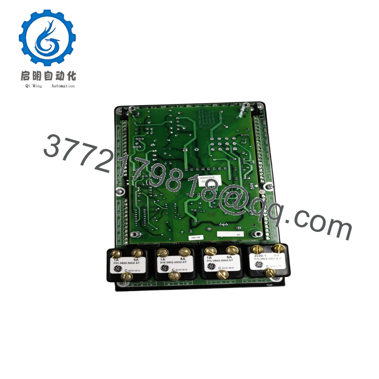
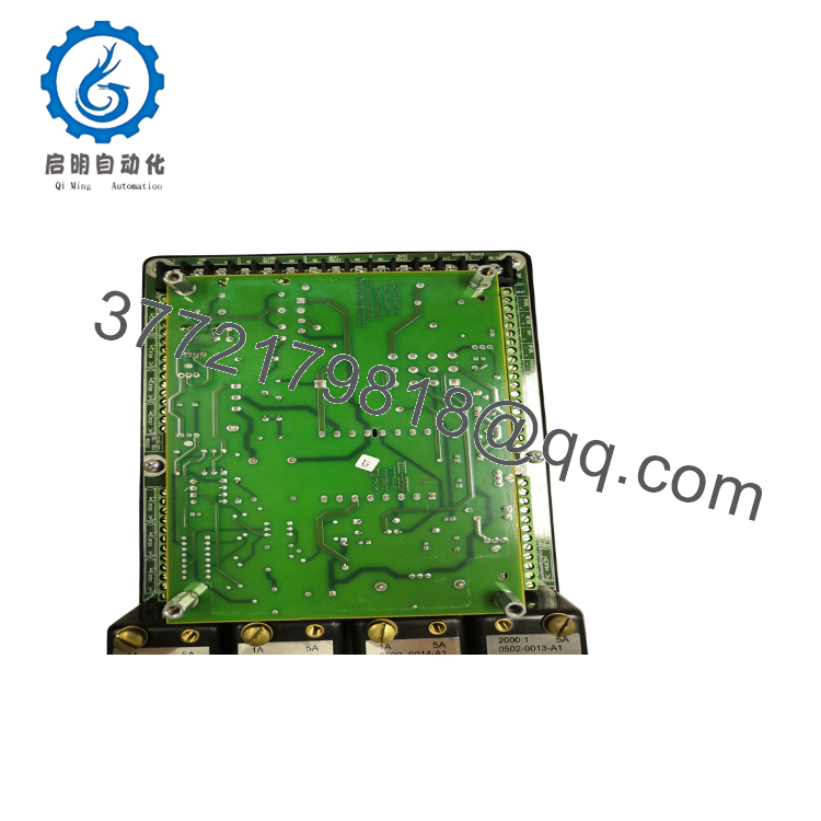
The GE 269PLUS-100P-HI is a microprocessor-based motor management relay designed to monitor, protect, and diagnose three-phase AC motors in critical industrial applications. It continuously tracks thermal capacity, phase currents, and RTD temperature inputs to protect high-voltage motors from overloads, phase unbalance, mechanical jams, and ground faults. This module serves as the primary defense mechanism for large pumps, compressors, and fans where unexpected motor failure halts entire production lines.
Procuring this module as New Surplus is a calculated risk-mitigation strategy for your plant’s Total Cost of Ownership (TCO). Because the 269 Plus series is legacy hardware, relying on refurbished components introduces high failure risks due to degraded internal capacitors and fatigued mechanical output relays. Maintaining 1–2 units of factory-sealed buffer stock on-site eliminates the standard 6-to-8-week lead time variability of sourcing secondary market items during an emergency shutdown. This approach secures OEM-level reliability at a fraction of the cost of a complete, unplanned system migration.

- 269PLUS-100P-HI
- 269PLUS-100P-HI
Installation & Configuration Guide
Stage 1: Pre-Installation (Prep & Safety)
- Execute full lock-out/tag-out (LOTO) procedures on the motor starter or switchgear cubicle controlling the circuit. Verify zero voltage on both the primary power paths and the 120/240 V auxiliary control circuits.
- Put on a grounded ESD wrist strap and connect it to the bare metal framework of the enclosure panel before handling the replacement unit.
- Photograph the rear terminal blocks of the active relay to document the existing wiring topology.
- Read and record the programmed setpoints directly from the display of the old relay if it is still operational, noting the CT ratios and RTD configuration.
Stage 2: Removal
- Label each wire harness attached to the rear terminal blocks (Terminals 1 through 68) to prevent cross-wiring.
- Disconnect the terminal blocks using a calibrated terminal screwdriver. Do not pull on the wire insulation.
- Loosen the four panel-mounting brackets securing the unit to the cutout.
- Slide the relay forward through the front of the panel cutout, taking care not to scrape the chassis or catch remaining wires on the rear housing.
Stage 3: Installation (Clone & Seat)
- Inspect the new surplus 269PLUS-100P-HI for physical integrity and verify the rear terminal label matches your original module configuration.
- Slide the module into the standard panel cutout. Tighten the four mounting brackets evenly to achieve a positive NEMA 12 seal against the panel face.
- Reattach the terminal blocks according to your labeled schematic and reference photographs. Tighten screws to the OEM-specified torque of 1.0 N·m (9 lb·in) to ensure robust electrical contact for CT circuits.
Stage 4: Power-On & Testing
- Disconnect the motor load breakers so that only control power is supplied during the initial boot phase.
- Energize the auxiliary control power rail (100–240 VAC). Verify the front LCD initializes and displays the system status without triggering an immediate “Err” code.
- Use the front keypad to manually input the recorded setpoint matrix, paying strict attention to the Phase CT Ratio and Motor Full Load Amps (FLA).
- Run a front-panel relay test to simulate a trip and confirm that the auxiliary contacts cleanly open and close the breaker trip circuit before restarting the motor.
Firmware/Software Versions & Upgrade Notes
The 269PLUS-100P-HI uses internal firmware chips that dictate its Modbus register mapping and RTD diagnostic capabilities. The standard recommended firmware for mature deployments is Revision 4.0 or higher, which addresses historical communication timeouts on legacy RS485 loops.
When replacing an older unit (e.g., Rev 2.x or 3.x), be aware that register addresses for automated SCADA data retrieval may shift. Do not attempt to field-flash firmware chips on a new surplus card without identical factory-labeled ROM replacements. A mismatch between the relay firmware version and your PLC communication drivers can cause instantaneous protocol errors, rendering the remote monitoring system blind.
Frequently Asked Questions (FAQ)
Q: Why is this New Surplus unit priced higher than refurbished versions online, but lower than original factory list prices?
A: Refurbished units are typically cleaned externally, but contain aged internal components like power supply capacitors and mechanical relays that have logged thousands of running hours. Our New Surplus inventory consists of genuine, unused hardware from excess project inventory and clean climate-controlled storage. You are paying a slight premium over a used gamble to secure zero-wear backplane connection points, original internal component life, and absolute operational uptime.
Q: Is the 269PLUS-100P-HI classified as an obsolete product? How does that impact my spare parts strategy?
A: Yes, the GE Multilin 269 Plus series is in the mature/discontinued phase of its product lifecycle. This makes vendor consolidation and strategic hoarding critical. You cannot rely on just-in-time (JIT) delivery from the factory. We advise keeping 1–2 units as a dedicated site insurance policy to prevent extensive downtime or an forced, expensive switchgear retrofit if an active relay fails.
Q: Can I hot-swap this relay while the motor is running?
A: Absolutely not. The 269PLUS-100P-HI handles direct connections to Current Transformers (CTs). Disconnecting a terminal block while a CT circuit is energized will cause an open-circuit condition, generating dangerously high voltages that will destroy the terminal block and pose an immediate arc-flash hazard to personnel. Always isolate primary power before touching connections.
Q: Does this unit retain its programmed parameters when control power is lost?
A: Yes. Setpoints are written directly to non-volatile EEPROM memory within the device. It does not require a continuous auxiliary power supply or a battery backup to maintain its configuration matrix during a power outage or extended storage in a warehouse.
Q: What kind of warranty coverage applies to this surplus module?
A: We back this New Surplus module with a complete 2-year industrial warranty from the date of shipment. This matches or exceeds original OEM protection periods, providing full assurance that the hardware will function exactly as intended when deployed into your active control panel.



