
 WhatsApp: +86 16626708626
 Email:
  Phone: +86 16626708626
Description
Key Technical Specifications
| Parameter | Value |
| Control Power Input | 40–265 VAC (50/60 Hz) / 50–300 VDC |
| RTD Inputs (R Option) | 12 channels (software-selectable for Stator, Bearing, Ambient, or Driven Equipment) |
| Metering Package (M Option) | Advanced power tracking: V, kW, kvar, kVA, PF, Hz, MWhrs |
| Current Inputs | Three-phase CTs (1 A or 5 A secondary) plus dedicated Ground CT input |
| Analog Outputs | 4 isolated channels total (1 base + 3 added via M option), user-configurable |
| Communications | 1 front RS232 port, 3 rear RS485 ports supporting Modbus RTU |
| Overload Protection Curves | 15 standard curves plus integrated FlexCurve™ custom profile modeling |
| Data Diagnostics | 512 Event Record Capacity, Oscillography, Motor Starting Data Logger |
| Operating Temperature | −40 to +60 °C (−40 to +140 °F) |
| Enclosure Protection | IP50X rating |
Product Introduction & Supply Chain Strategy
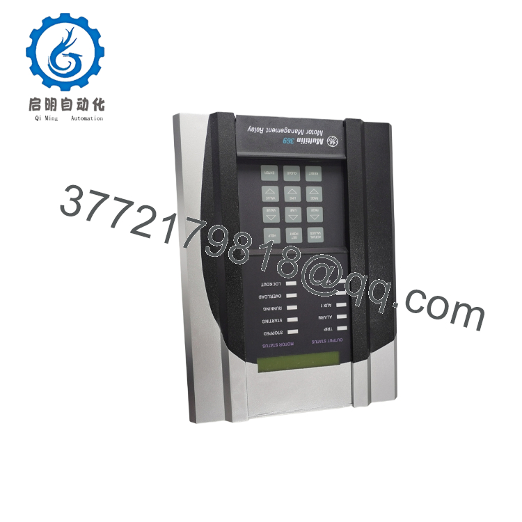
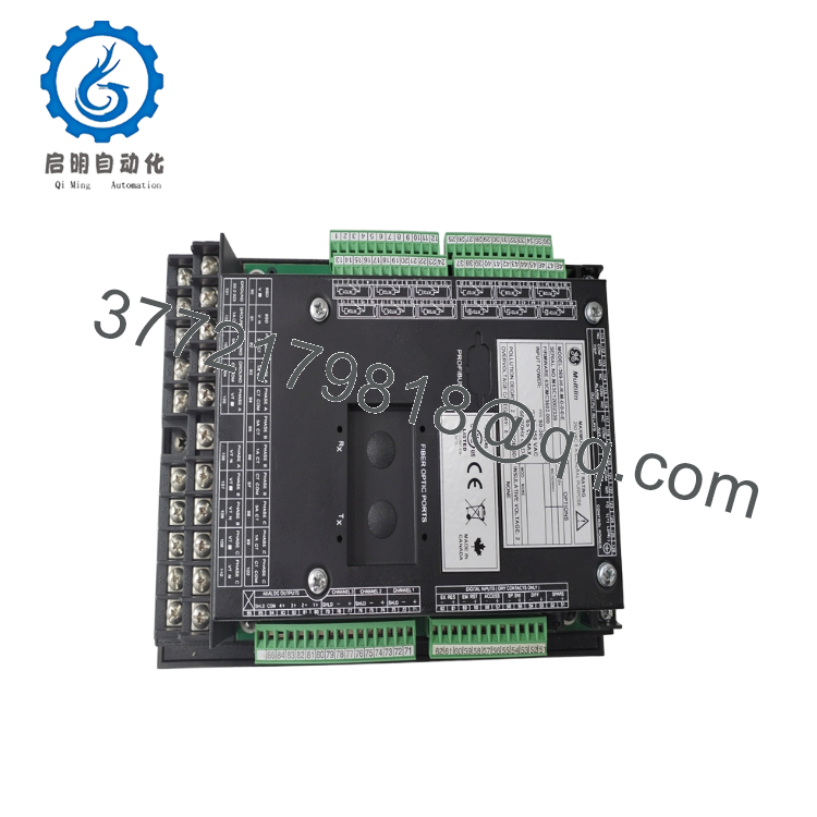
The GE Multilin 369-HI-R-M-0-0 is an advanced digital motor protection system designed to safeguard medium-sized, high-voltage AC motors and their associated mechanical assets. Equipped with the “R” suffix for 12 physical RTD inputs and the “M” suffix for comprehensive power monitoring, this unit tracks real-time thermal capacity, phase current unbalance, and detailed power metrics like power factor and megawatt-hours. Its built-in adaptive logic uses learned motor data—such as inrush current profiles and cooling rates—to dynamically tailor its protective curves, preventing mechanical damage in down-hole pumps, large fans, and variable frequency drive applications.
Sourcing this specific configuration as New Surplus is an essential capital-preservation decision for critical industrial drivetrains. Because the 369 series is in its legacy lifecycle stage, lead times for direct OEM factory orders can stretch out to 8 or 12 weeks, exposing your facility to major stock-out incidents. Choosing cheaper, third-party refurbished hardware exposes your automated systems to hidden internal fatigue from aged power circuits and worn output contact relays. Retaining a factory-sealed, unused surplus unit directly on your plant shelf cuts emergency repair times down to zero hours, maintaining total infrastructure reliability while avoiding the extreme upfront expenditures of a forced, multi-tier control room migration.

- 369-HI-R-M-0-0
- 369-HI-R-M-0-0
Installation & Configuration Guide
Stage 1: Pre-Installation (Prep & Safety)
- Verify complete isolation of the motor cubicle. Execute full lock-out/tag-out (LOTO) protocols on the primary breaker and all auxiliary control transformer power paths.
- Put on an ESD wrist strap connected directly to a verified chassis ground point to avoid static discharge damage to the internal microprocessors.
- Use the front keypad or the EnerVista 369 Setup software via the front RS232 port to download and back up all active software settings and custom FlexCurve parameters from the legacy relay.
- Document the physical position of all input wiring connections on the backplane terminals.
Stage 2: Removal
- Unplug or disconnect the wire harness connectors attached to the rear panel terminal strips. Do not apply force directly to individual control wires.
- Ensure the connected Current Transformers (CTs) are safely shorted via a shorting block. Never open-circuit an energized CT path.
- Loosen the panel bracket mounting hardware located on the perimeter of the chassis housing.
- Pull the heavy relay core smoothly out from the panel face cutout, keeping the unit horizontal to avoid damaging adjacent wiring.
Stage 3: Installation (Clone & Seat)
- Slide the new surplus 369-HI-R-M-0-0 into the clear cutout space, ensuring the rear orientation lines up correctly with existing terminal leads.
- Hand-tighten the integrated panel clamp screws evenly across the unit body to guarantee an unbroken IP50X dust-resistant seal against the panel face.
- Reconnect the rear terminal wiring matching the documented blueprint. Torque all screw connection points down to 1.0 N·m (9 lb·in) to prevent loose terminal failures during machine vibration.
Stage 4: Power-On & Testing
- Disconnect or isolate the main power contacts, leaving only the auxiliary control loop live.
- Flip on the 40–265 VAC / 50–300 VDC control power rail. Ensure the 40-character alphanumeric front LCD illuminates cleanly and cycles to a normal “Stopped” motor state indicator light.
- Upload your original software settings via the EnerVista package, verifying the active current parameters match the real-world CT transformation ratios.
- Execute an automated self-test routine through the utility menu to confirm all four output relays cleanly operate their designated trip and warning alarms before putting the underlying motor back into service.
Firmware/Software Versions & Upgrade Notes
The 369-HI-R-M-0-0 relies on specific internal firmware configurations that establish communication register locations and historical event logging matrices. If replacing an older revision card, ensure your SCADA Modbus drivers match the specific data map used by the incoming firmware version.
Be cautious of running mixed configurations; shifting firmware versions on mature systems without adjusting master system configurations can break communication handshakes, disabling remote monitoring tools. Always cross-reference the software version labeled on the chassis side sticker with your central control workstation specifications prior to executing the initial hardware hot-boot.
Frequently Asked Questions (FAQ)
Q: How does the “R” and “M” designation affect my inventory strategy when swapping this with a baseline 369 unit?
A: The “R” designates 12 built-in RTD temperature sensors, and the “M” denotes the full power metering hardware add-on package. If your active prints require temperature feedback from stator or bearing sensors along with power monitoring (kW, kvar, PF), a baseline 369 model will not work. Maintaining this exact 369-HI-R-M-0-0 configuration as a warehouse spare ensures you can cover every potential 369 failure point across the entire site, making it a highly effective universal asset block.
Q: Are these units truly new, or are they pulled parts polished up to look like surplus?
A: Every piece of inventory labeled as New Surplus or New Original is completely unused, featuring zero wear on backplane terminal connectors and untouched internal micro-circuits. These are sourced from uninstalled capital project reserves and climate-controlled storage pools. We enforce a zero-tolerance policy against refurbished or pulled scrap masquerading as authentic surplus.
Q: What are the dangers of choosing a cheaper refurbished 369 relay over an original surplus unit?
A: Refurbished protection equipment introduces real, unmeasured secondary risks. While the front faceplate might look clean, the internal electrolytic power capacitors and small mechanical trip contacts inside a used relay carry logged operational hours, which accelerates component degradation. A failure on a used 300 part can result in 50,000+ of unplanned downtime if a medium-voltage motor burns out without the relay triggering a safety shutoff.
Q: Does this relay store its operating logs and trip history when disconnected from power?
A: Yes. The unit saves up to 512 historical event records, motor starting data logs, and internal oscillography data directly within non-volatile onboard memory. This telemetry data stays intact inside warehouse storage and will not clear out when the control circuit loses primary power.
Q: What coverage protects my procurement investment on this legacy hardware?
A: We back this item with a complete 12-month operational warranty starting from your logistics delivery date. This warranty guarantees that the surplus unit functions identical to factory-new standards, giving your site procurement teams complete peace of mind when backing up legacy automated plants.



