
 WhatsApp: +86 16626708626
 Email:
  Phone: +86 16626708626
Description
3. Key Technical Specifications
| Parameter | Value |
|---|---|
| Manufacturer | GE Multilin |
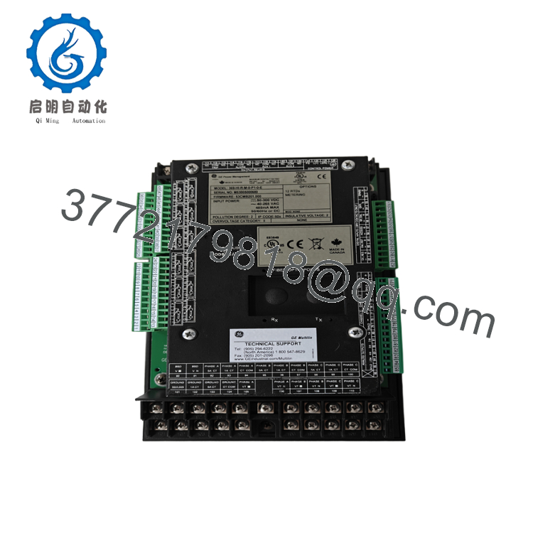
| Model | 369-HI-R-M-0-P1-0-E |
| Product Type | Digital Motor Protection Relay |
| Series | Multilin 369 |
| Control Power | 50–300 VDC / 40–265 VAC |
| RTD Inputs | 12 built-in RTD inputs |
| Metering | Voltage, power, energy, frequency, demand metering |
| Communication | Profibus DPV1 |
| Front Port | RS232 programming port |
| Rear Communications | RS485 (Modbus RTU) plus Profibus DPV1 |
| Fiber Port | Not installed |
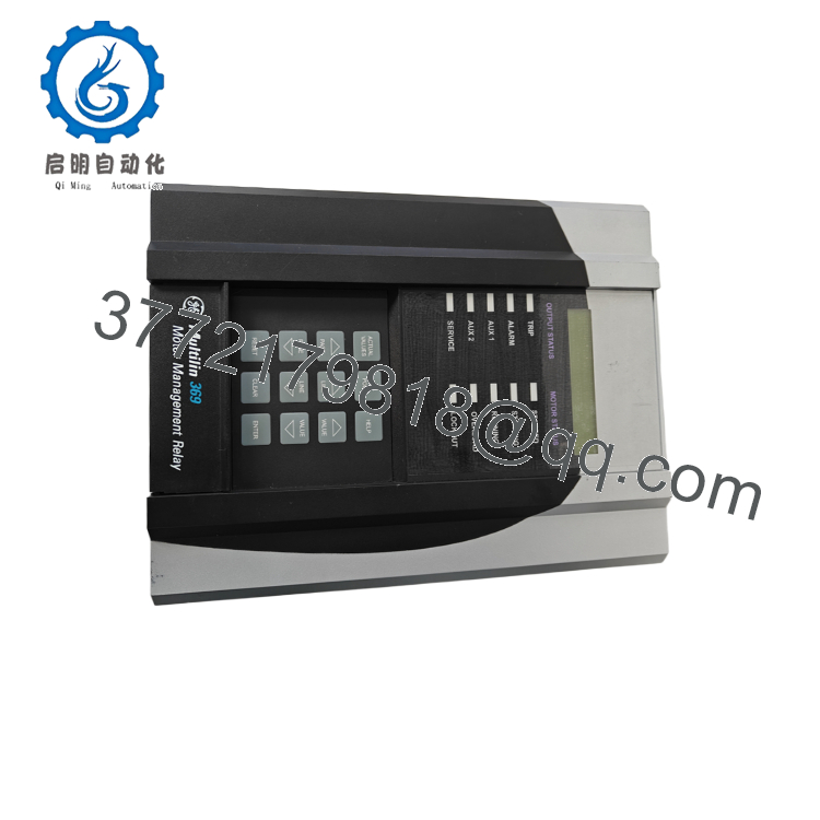
| Display | LCD with Enhanced Faceplate |
| Analog Outputs | Four (with Metering option) |
| Protection Functions | Thermal overload, locked rotor, stall, current unbalance, phase loss, ground fault, undercurrent, overtemperature |
| Mounting | Panel mount (non-drawout) |
| Approximate Weight | 4.5 kg (10 lb) |
The Multilin 369 has been discontinued by GE Vernova. The recommended successor platform is the Multilin 859 Motor Protection System.
4. Product Introduction
The GE Multilin 369-HI-R-M-0-P1-0-E is a digital motor management relay engineered for protecting and monitoring medium-voltage and large low-voltage AC motors. It combines comprehensive protection, thermal modeling, motor diagnostics, event recording, and industrial communications into a single relay for critical process industries.
This configuration includes the HI universal control power supply, 12 built-in RTD temperature inputs, the advanced metering package, Profibus DPV1 communications, and Enhanced Diagnostics. It is well suited for applications requiring continuous motor condition monitoring and direct integration with Profibus-based PLC and DCS systems.

- 369-HI-R-M-0-P1-0-E
- 369-HI-R-M-0-P1-0-E
5. Installation & Configuration Guide
Stage 1 – Pre-Installation Preparation (10 Minutes)
⚠️ Safety First
- Notify operations personnel before removing motor protection.
- Lock out and tag out all motor feeders.
- Isolate relay control power.
- Wait at least 5 minutes for internal capacitors to discharge.
- Verify zero voltage with a calibrated multimeter.
Tools Required
- ESD wrist strap
- PH1 screwdriver
- Fluke 115 (or equivalent) multimeter
- Wire markers
- Smartphone for wiring documentation
- Laptop with GE EnerVista 369 Setup software
- Profibus diagnostic tool (recommended)
Data Backup
- Export relay settings.
- Save event records and oscillography.
- Record firmware revision.
- Photograph terminal wiring.
- Document Profibus node address and network parameters.
- Record RTD assignments and alarm settings.
Stage 2 – Removing the Existing Relay (5 Minutes)
- Remove the relay cover if required.
- Label all power, CT, RTD, and communication wiring.
- Disconnect terminal blocks carefully.
- Remove mounting hardware.
- Withdraw the relay straight out to prevent connector damage.
⚠️ Retain the original relay until the replacement has passed all commissioning tests.
Inspect:
- Terminal tightness
- Backplane condition
- Dust accumulation
- Signs of overheating
Stage 3 – Installing the New Relay (10 Minutes)
- Wear an ESD wrist strap.
- Verify the complete model number:
369-HI-R-M-0-P1-0-E - Install the relay securely.
- Reconnect CT, RTD, power, and communication wiring.
- Restore the saved configuration.
- Configure the Profibus DPV1 network address.
- Verify RTD channels and CT ratios.
Self-Checklist
- ☑ Correct model installed
- ☑ RTD wiring verified
- ☑ CT polarity confirmed
- ☑ Profibus node address correct
- ☑ Ground connection secure
- ☑ Configuration restored
Stage 4 – Power-On & Commissioning (10–15 Minutes)
Before Energizing
- Verify insulation resistance where applicable.
- Confirm no control power shorts.
- Ensure CT secondary circuits remain closed.
- Verify Profibus termination settings.
Commissioning Steps
- Apply control power.
- Observe the relay startup sequence.
- Confirm the RUN status.
- Connect using EnerVista software.
- Verify firmware revision.
- Confirm Profibus DPV1 communication with the PLC or DCS.
- Verify RTD temperature readings.
- Perform secondary current injection tests.
- Confirm trip and alarm outputs.
- Return the motor to service after successful functional testing.
⚠️ Troubleshooting
Profibus communication failure
- Verify node address.
- Check baud rate and GSD file compatibility.
- Confirm bus termination.
- Inspect cable shielding.
Temperature alarms immediately after startup
- Check RTD wiring polarity.
- Verify RTD type configuration.
- Inspect sensor continuity.
6. Frequently Asked Questions (FAQ)
Q1. Can this relay be replaced without shutting down the motor?
No. The Multilin 369 is not designed for hot swapping. Always isolate control power before removal to avoid equipment damage and loss of motor protection.
Q2. What does the “R” option provide?
The R option adds 12 built-in RTD inputs, allowing direct monitoring of winding, bearing, and ambient temperatures. This improves thermal protection accuracy and supports predictive maintenance.
Q3. What does the “P1” option add?
The P1 option provides a Profibus DPV1 communication interface, enabling integration with Siemens and other Profibus-compatible PLC and DCS platforms while supporting expanded acyclic communication compared with standard DP.
Q4. Is the GE Multilin 369 still manufactured?
No. GE Vernova has discontinued the Multilin 369 product line. The recommended replacement for new installations is the Multilin 859, although many plants continue supporting existing 369 installations with spare units.
Q5. Will my protection settings be lost during replacement?
Not if you create a backup beforehand. Export the complete configuration using GE EnerVista 369 Setup and document all communication parameters before removing the original relay.
Q6. Why should I verify the firmware before installation?
Firmware revisions can affect communication behavior, event logging, and protocol compatibility. Before replacing the relay, compare the firmware version of the new unit with the installed relay to minimize commissioning time and avoid unexpected communication issues.
Q7. What quality inspections should be completed before shipment?
A complete inspection should include:
- OEM serial number verification
- Visual inspection for corrosion or repair marks
- Power-on functional test
- LCD, keypad, and LED verification
- RTD input simulation
- Profibus DPV1 communication test
- Relay output verification
- Firmware version documentation
- Final QC inspection
- ESD-safe packaging with anti-static protection
For planned outages, requesting a functional test report and firmware record before shipment helps ensure compatibility with existing protection schemes and shortens startup time.



