
 WhatsApp: +86 16626708626
 Email:
  Phone: +86 16626708626
Description
Key Technical Specifications
| Parameter | Value |
| Control Power Supply | 24–48 VDC / 20–48 VAC (50/60 Hz) |
| RTD Inputs | 0 channels (Base configuration, no R option hardware installed) |
| Metering Package (M Option) | Fully integrated (V, kW, kvar, kVA, PF, Hz, MWhrs) |
| Enhanced Diagnostics (E Option) | Includes Motor Health Report, Start Data Logger, and Security Audit Trail |
| Phase Current Inputs | 1 A or 5 A secondary (field selectable) |
| Analog Outputs | 4 isolated channels total (1 base + 3 enabled via M option) |
| Communications | 1 front RS232 port, 3 rear RS485 ports supporting Modbus RTU |
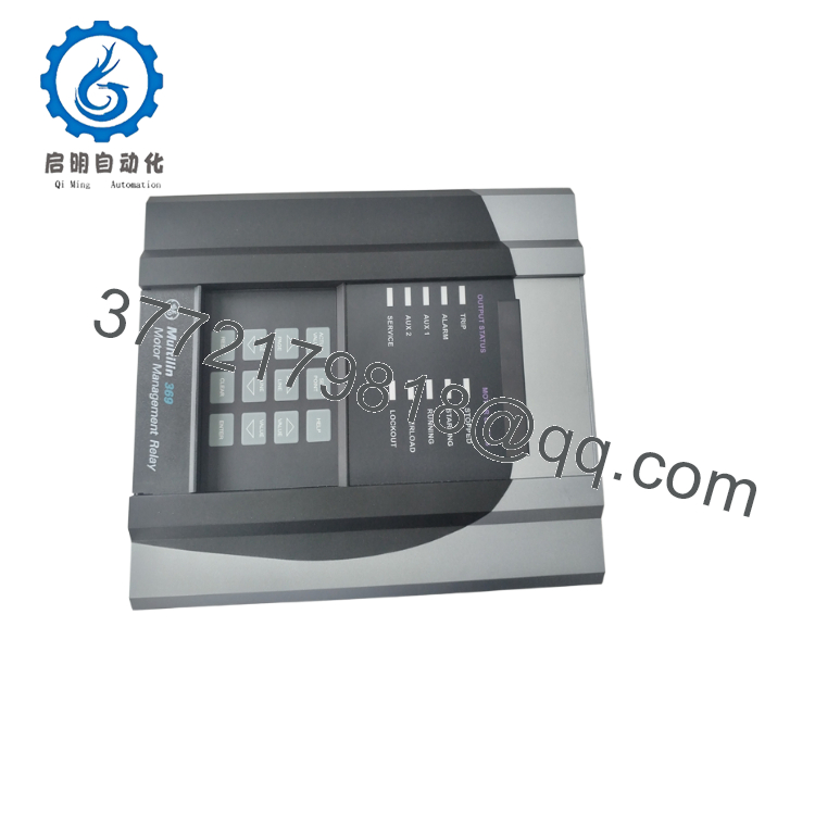
| Display Configuration | 40-character alphanumeric LCD with enhanced motor status LEDs |
| Enclosure Rating | IP50X Dust-Resistant Front Faceplate |
| Operating Temperature | −20 to +60 °C (−4 to +140 °F) |
Product Introduction & Supply Chain Strategy
The GE Multilin 369-LO-0-M-0-0-0-E is a digital motor management relay configured for low-voltage auxiliary control systems and comprehensive electrical asset monitoring. Distinct from high-voltage versions, this model features a “LO” power supply input optimized for 24–48 VDC battery banks or low-voltage AC rails. The “M” modifier injects complete power metering algorithms directly into the processing engine, while the final “E” identifier equips the device with an enhanced diagnostic faceplate and an advanced motor health logger. It serves as a defensive monitoring node for industrial pumps, compressors, and fans operating within variable frequency drive or low-voltage control setups.
Procuring this exact hardware variation as New Surplus is a necessary move to protect your plant’s Total Cost of Ownership (TCO). Because this legacy series has transitioned to a mature lifecycle stage, factory lead times are highly unpredictable, creating major lead time variability during unexpected maintenance events. Relying on lower-cost refurbished components compromises your monitoring accuracy due to degraded internal component lifecycle wear on the analog-to-digital converter circuits. Maintaining 1–2 factory-sealed surplus units directly on your warehouse shelves prevents critical stock-out incidents, keeping your system infrastructure online without the major costs of an premature system overhaul.
Installation & Configuration Guide
Stage 1: Pre-Installation (Prep & Safety)
- Execute full lock-out/tag-out (LOTO) protocols across the motor control cubicle. Ensure complete power isolation on both the primary feed lines and the auxiliary 24/48 V control power circuit.
- Fasten a grounded ESD wrist strap to your arm and attach it to an unpainted metal section of the electrical cabinet frame before touching the relay housing.
- Establish a serial connection to the active relay using EnerVista 369 Setup software on a field laptop. Download and back up all active parameters, protection curves, and system log records.
- Label and photograph the rear terminal point layout to guarantee clear identification during installation.
Stage 2: Removal
- Safely short out all connected phase and ground Current Transformers (CTs) at the external shorting block. Never open-circuit an active CT line to prevent generating high-voltage terminal arcs.
- Unplug the terminal block wiring connectors carefully from the rear terminal pins. Avoid applying any pull pressure to individual control wires.
- Loosen the four mounting bracket clamps positioned on the outer flange of the relay body.
- Push the housing gently forward out through the front panel opening, keeping the unit level to prevent scraping nearby components.
Stage 3: Installation (Clone & Seat)
- Position the new surplus 369-LO-0-M-0-0-0-E into the standard panel cutout gap.
- Tighten the perimeter mounting clamps in a balanced pattern to compress the rear gasket, making an authentic IP50X dust-tight seal.
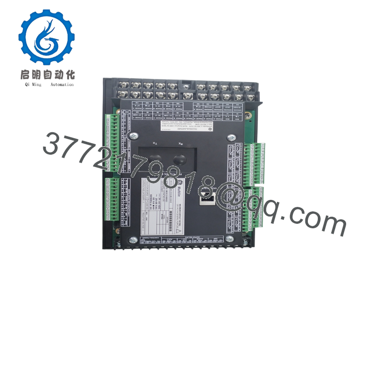
- Reattach the rear terminal blocks onto the corresponding pin patterns. Torque all wiring screws down to 1.0 N·m (9 lb·in) to secure the connection pins against machinery vibration.
Stage 4: Power-On & Testing
- Disconnect the main motor power line contacts, allowing only the low-voltage auxiliary supply circuit to operate.
- Turn on the 24–48 VDC control power rail. Verify the upgraded 40-character LCD display lights up and stabilizes into a normal “Stopped” or “Ready” screen.
- Upload the saved setpoint profile using the EnerVista interface tool, verifying that the configured CT ratios correspond with your actual print designs.
- Execute an automated relay diagnostic run via the internal menu system to confirm that the trip contacts fire and interrupt the control safety chain before starting the motor.

- 369-LO-0-M-0-0-0-E
- 369-LO-0-M-0-0-0-E
Firmware/Software Versions & Upgrade Notes
The 369-LO-0-M-0-0-0-E utilizes distinct internal firmware versions that control the data address register maps for Modbus network architectures. If your plant is replacing older versions, check that the new unit’s firmware matches the communication drivers configured within your master SCADA or DCS system.
Shifting firmware versions on older networks can sometimes break communication handshakes, leaving local operations blind to remote data. Always review the software revision label located on the side panel of the surplus chassis prior to initiating the initial system startup sequence.
Frequently Asked Questions (FAQ)
Q: What do the “LO” and “0” markers indicate in this model number code, and how do they alter my spare parts strategy?
A: The “LO” indicates a low-voltage power supply rating (24–48 VDC or 20–48 VAC), while the following “0” means this unit has no internal RTD temperature sensor options installed. If your setup uses 120/240 V control rails or requires direct stator temperature inputs, this module will not fit that application. Sourcing this precise low-voltage configuration as a warehouse spare ensures you can cover low-voltage, metering-heavy control setups across the facility.
Q: How do I know these parts are truly New Surplus and not just pulled components that have been cleaned up?
A: Every item we classify as New Surplus or New Original is guaranteed to be completely unused, showing pristine terminal contacts and flawless internal circuitry. This hardware is sourced from uninstalled system expansion stock and climate-controlled storage facilities. We maintain a strict policy against used or refurbished items masquerading as original surplus.
Q: Why should our facility choose original surplus instead of cheaper refurbished 369 options?
A: Refurbished equipment introduces serious unmeasured risks into critical safety systems. While the external casing may look clean, the internal power capacitors and tiny mechanical components carry recorded operating hours, which speeds up component breakdown. A failure on a used 300 part can result in 50,000+ of unplanned downtime if a medium-voltage motor burns out without the relay triggering a safety shutoff.
Q: Will the programming setup and event logs stay saved in the relay when it is in warehouse storage?
A: Yes. All parameters, protective curve definitions, and historical logs are saved directly to non-volatile onboard EEPROM memory. This data will remain completely intact during years of storage and does not depend on internal battery packs or continuous control power to preserve configuration integrity.
Q: What kind of warranty program protects this specific legacy module?
A: We provide a comprehensive 12-month replacement warranty from your logistics delivery date on this item. This coverage guarantees that your surplus unit will meet or exceed standard OEM functional specifications, giving procurement teams complete peace of mind when backing up older industrial facilities.



